4 Port Optical Circulator Manufacturer: Define Every Directional Route Before Ordering
A fourth fiber lead is useful only if the instrument needs the extra directional route. Moving from three ports to four without drawing that route can add loss and mounting difficulty while solving no actual problem. A 4 port optical circulator manufacturer should review the required port transitions and wavelength before proposing a replacement. Compare Feiyi’s three-port optical circulator with its four-port version when your assembly genuinely requires another destination. Define the path entering each active port first.
This decision is relevant to optical-instrument builders and service engineers modifying a directional network or measurement route. The circulator is a passive routing component; it is not a software-selected optical switch. A request for “one more port” must therefore identify where light will enter and where the selected device is expected to send it.
A 4 port optical circulator manufacturer needs every required directional transition
Feiyi’s three-port entry identifies the sequence Port 1 to Port 2 to Port 3. Its four-port entry identifies Port 1 to 2, Port 2 to 3 and Port 3 to 4. Write those transitions onto the proposed instrument drawing and mark the source or receiving function of each connection. Do not invent a Port 4-to-Port 1 path merely from the word “circulator”; that route is not established by the listed configuration.
For an instrument adding a second directional receiving stage, a light path entering Port 3 and leaving Port 4 may be the reason to consider the larger unit. If the design still uses only the original two forward transitions, the added topology needs another justification. A unused fourth lead does not make the remaining routes inherently better or establish a lower-loss replacement.
The three-port connection cannot be inferred from fiber colors alone
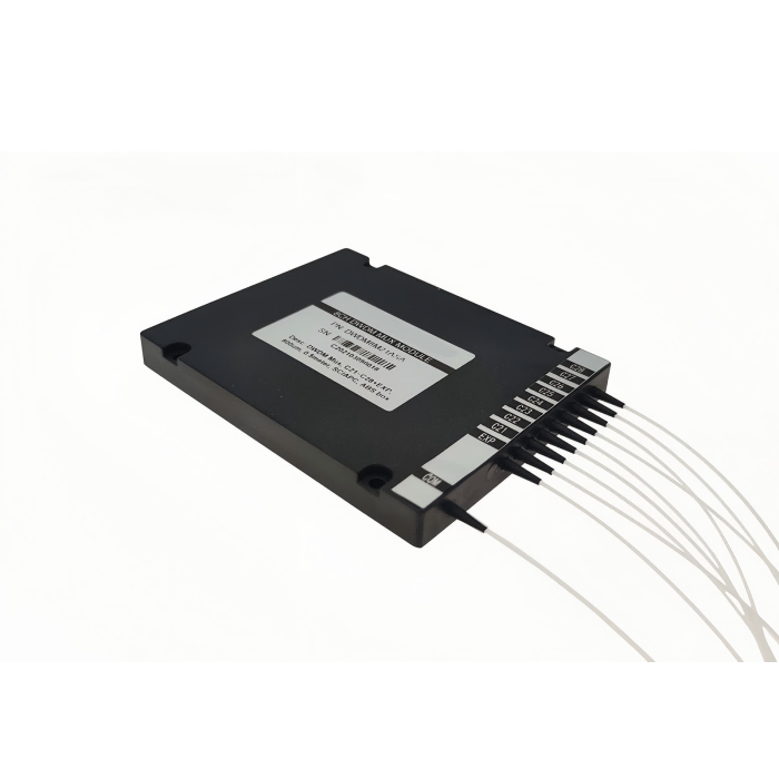
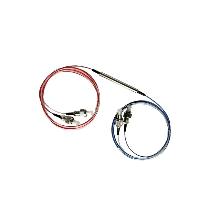
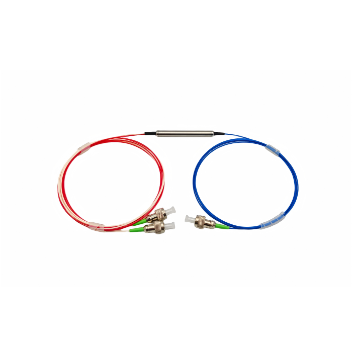
Port identifiers should follow the actual supplied unit and approved drawing. A photograph can help recognize the package, but it cannot prove which installed lead is Port 1. When replacing an old circulator, preserve the original route identities before disconnecting it. Ask for labels that remain usable after the leads are routed into the instrument, rather than relying on the temporary arrangement in a shipping box.
AFW’s circulator explanation describes the directional role of three- and four-port devices. Thorlabs’ circulator documentation also distinguishes intended forward routes from other paths. These references help interpret a route drawing; their loss or power figures should not be copied into the selected Feiyi configuration.
Three-port and four-port circulator packages change the replacement envelope
The Feiyi four-port telecom product lists a cylindrical package of 5.5 mm diameter by 68 mm length. The three-port entry lists 5.5 mm diameter by 38 or 50 mm length and a 90 ×20 ×10 mm ABS option. A fourth directional path can therefore bring a different physical envelope. Confirm the chosen package and fiber exits before retaining the existing instrument bracket.
The four-port entry lists typical insertion loss of 1.0 dB and maximum insertion loss of 1.2 dB. Attach those values to the required tested transitions and delivered connector condition. The three-port product’s routing information does not authorize treating those four-port values as identical for every model or interpreting an unclear table label as a precise loss guarantee.
A longer four-port housing needs lead clearance as well as mounting space
A service engineer may find enough room for the 68 mm cylinder but insufficient clearance for the outgoing leads. The relevant envelope includes fiber exits, support and the connector service loop. A mount that loads one lead while retaining the housing can change the installed optical condition. Agree the permitted retention and routing arrangement for the selected package rather than forcing it into the old three-port footprint.
The ordering options include bare fiber or 900 µm loose-tube choices, different connector finishes and lead lengths. These selections belong to the replacement drawing. If the old assembly was splice-connected and the new one adds detachable connectors, the accepted loss path has changed. Review the new interface allowance instead of claiming that the larger device alone determines the complete route loss.
A wavelength migration requires a new circulator version
The telecom three- and four-port entries list 1310 ±30 or 1550 ±30 nm variants. Choose the actual band used by the source and receiving system. A fiber that physically transports another wavelength does not prove that the circulator’s directional isolation and loss remain suitable there. A service replacement must preserve the approved wavelength as well as the port count.
Feiyi’s 1060 nm three-port circulator lists an operating interval of 1055–1065 nm, with 1.8 dB typical and 2.2 dB maximum insertion loss. Its fiber is identified as Corning HI1060, and its package as 34 ×8.4 ×8.4 mm. These are different optical and mechanical conditions from the telecom cylinder. Do not carry the telecom loss limit into this wavelength migration.
A nominal 1060 nm source still needs its actual tuning interval
A source described by its center wavelength may tune beyond the selected component’s narrow band. For the Feiyi 1060 nm entry, compare the required source interval with 1055–1065 nm before approving the route. If the source operating conditions exceed it, request a specifically confirmed alternative. Do not broaden the band by treating a similar product name as proof that the current unit covers the entire desired interval.
The 850/980 nm three-port entry identifies 850 ±20 or 980 ±20 nm variants. Confirm which is supplied and obtain its approved fiber and power conditions. Its wavelength alternatives are not a declaration that a single unit simultaneously serves both bands, and a broad ordering list should not override the selected performance specification.
Low PDL and polarization maintenance are different circulator requirements
The ordinary circulator entries include polarization-dependent loss values. PDL describes loss variation with input state. It does not establish that an optical route maintains a specified PM axis. If an instrument’s receiver requires a stable polarization reference, identify that requirement separately before accepting an ordinary single-mode circulator solely from its low-PDL entry.
Feiyi’s PM1550 circulator is the separate range to evaluate for that requirement. It specifies PM1550 fiber, fast- and slow-axis information and a minimum extinction-ratio entry. Its three-port routing remains subject to its own approved axis and connector arrangement. It should not be represented as a four-port PM replacement without a specifically confirmed configuration.
The connector key becomes part of a PM route’s acceptance boundary
For the PM version, identify how each delivered connector reference agrees with the intended axis. For the ordinary version, preserve the appropriate connector finish and mating interface without inventing a PM requirement. Both need endpoint definitions, but the polarization-sensitive instrument has an additional axis condition. A common connector housing cannot make these two acceptance scopes interchangeable.
Agiltron’s PM circulator documentation provides background on polarization-preserving directional routing. The procurement implication is to select a documented PM construction when that property is needed, rather than inferring it from low PDL. Feiyi’s selected device still needs its own applicable path and polarization limits.
Test the added circulator route before approving the modified instrument
For a three-to-four-port upgrade, begin with the previously used transitions and the new required transition as separate checks. Confirm which input port is illuminated and which destination receives the intended signal. Measure leakage where it matters to the instrument. A test only through the old path would leave the reason for adding the fourth port unverified.
The four-port telecom entry lists maximum optical power of 300 mW. Define the power entering every active route and confirm the delivered construction. A receiver collecting little light does not establish the power seen at another port. Similarly, the 1060 nm entry lists 300 mW, but another wavelength-family description should not be treated as a universal higher-power authorization.
Environmental limits also vary. The four-port telecom entry lists −10 to +75 °C, while the 1060 nm entry lists 0 to +50 °C. If the instrument changes wavelength or topology, review the required operating environment instead of preserving the old temperature allowance automatically. A wider storage range belongs to transport conditions, not proof of optical operation.
For receiving and installation, ask for protected terminations and port identifiers tied to the approved drawing. Agree how an unused port should be handled for the selected device and system; do not improvise a reflective connection because the instrument has no immediate destination for it. Keep the spare route accessible and identified if the modification is intended for future expansion.
A fourth circulator port should have a receiving condition on the drawing
Identify the optical element connected to Port 4 and its expected input conditions. A useful additional route might terminate at another instrument stage, but its loss and leakage requirements belong to that destination. Do not infer acceptance merely because light appears there. The added stage should receive the intended wavelength and enough usable power under the actual source conditions, with unwanted routes assessed separately where they affect the measurement.
For a replacement without a topology change, test the physical port identity before reusing the old instrument calibration. The three-port telecom and 1060 nm products can look similar in an assembly image, but their wavelength and package entries differ. A correct lead number on the wrong wavelength version remains an incorrect replacement. Confirm both the actual unit identification and the route it makes before closing the optical housing.
The four-port entry lists return loss of at least 50 dB and PDL no greater than 0.2 dB. These quantities address reflection and loss variation, respectively. Neither replaces the defined forward-path loss test or the required unwanted-route test. Keep their purposes separate in acceptance so a favorable reflection figure is not treated as evidence that the added directional transition has sufficient signal margin.
If the modified instrument uses a shorter lead or another connector finish to fit the longer cylinder, evaluate the delivered route at its new endpoints. The optical replacement has changed more than its port count. Preserve the selected finish, length and connector inclusion conditions in the approved file, and compare like measurement boundaries. That is more useful than asking for the original bench result to remain numerically unchanged after an interface redesign.
Where the supplier offers a package alternative, ask which performance limits apply to that actual construction. The three-port ABS option and cylindrical option serve different mounting situations. A mechanically convenient enclosure should not be accepted on an assumption about a different unit’s fiber exits or test reference. The proposed replacement should be identifiable as one complete optical and mechanical configuration.
Feiyi’s article on circulator principles and specifications gives broader context. Approve the modified instrument when the extra port performs the identified route, the wavelength version fits the source and the complete installed path meets its defined budget. If no useful fourth transition exists, preserve the smaller topology and spend the engineering effort on the route the instrument actually uses.
A 4 port optical circulator manufacturer order should name the tested route and delivered interface
A repeatable four-port order needs more than the phrase “same as sample.” Record the 1310 nm or 1550 nm wavelength selection, the Port 1 to 2, Port 2 to 3 and Port 3 to 4 sequence, the selected fiber protection, connector polish, lead length and the 5.5 mm by 68 mm package. If the accepted unit was tested without a connector condition that appears on the production build, document that interface change before comparing results.
For a distributor, three-port and four-port versions should remain separate item identities even when both are called optical circulators. The additional lead changes routing and the mechanical envelope, while 1060 nm products belong to another wavelength family again. Keeping those distinctions in the stock description reduces the chance that a visually similar part is shipped into a calibrated instrument.
For an OEM, attach incoming inspection to the exact route that matters in the assembly. A successful reading from Port 1 to Port 2 does not prove the added Port 3 to Port 4 transition. The fourth path should have its own receiving condition so the reason for choosing the four-port architecture is actually verified.