Choose a Fiber Optic Isolator Manufacturer for a Source With a Changing Polarization State
A source connected through ordinary single-mode fiber may see a changing input polarization, even when its optical power is stable. In that situation, choosing a PM-only transmission route can create an unnecessary alignment requirement. A fiber optic isolator manufacturer should evaluate the needed reverse protection under the actual input-state conditions. Feiyi’s polarization-insensitive isolator and mini version are relevant starting points for ordinary SM routes. Confirm the operating band and minimum isolation before choosing stage count or housing size.
For a telecom source, amplifier or measurement assembly, the purpose is to suppress unwanted reverse transmission while preserving usable forward power. The requirement is not that the isolator creates a stable polarization state. Low polarization-dependent loss and PM-axis preservation describe different properties, so keep the actual source and downstream needs visible in the order.
A fiber optic isolator manufacturer should compare minimum isolation with the source requirement
Feiyi’s standard polarization-insensitive unit lists 1310 or 1550 nm with a ±15 nm band. The single-stage entry has peak isolation of 42 dB and minimum isolation of 28 dB; the dual-stage entry has peak isolation of 56 dB and minimum isolation of 46 dB. The source-protection decision should use the applicable minimum condition, not assume that the peak number describes every wavelength and operating circumstance.
The forward-loss tradeoff is separately stated: typical insertion loss is 0.35 dB for the single stage and 0.4 dB for the dual stage, with maximum values of 0.55 and 0.6 dB. Decide whether the improved minimum reverse suppression is needed and whether the forward budget supports the selected version. A dual-stage label should not be treated as a universal reason to choose the larger isolation figure.
A 1550 nm source needs its actual band inside the isolator’s ±15 nm interval
A source with tuning, spectral width or changing center wavelength should be described by the required interval. A 1550 nm name alone does not establish that the complete source condition stays inside the chosen isolator band. Ask for the applicable minimum isolation and forward-loss conditions over that interval. This gives the manufacturer a concrete protection requirement rather than a request for the highest headline value.
AFW’s polarization-insensitive isolator information provides technical context for single- and dual-stage limits. Newport’s single-mode isolator documentation also separates a source-protection function from its selected device performance. Their numerical specifications should not be used as acceptance limits for Feiyi’s unit.
Polarization-insensitive isolation does not promise a fixed output polarization
The Feiyi standard product lists SMF-28e fiber and PDL no greater than 0.05 dB. PDL describes variation in loss with input state. It does not establish a preserved PM axis or turn an ordinary SM lead into a polarization-maintaining connection. If the receiving instrument separately requires a defined polarization, that interface needs its own optical design and documented component selection.
Imagine an amplifier source fed through a cable whose state changes during handling. A polarization-insensitive isolator can be a relevant protection choice when the transmitted state need not be fixed. If a later stage is polarization sensitive, the engineer must also establish what reaches that stage. Selecting an isolator with low PDL solves a loss-variation requirement; it does not eliminate the separate state requirement.
The standard SM isolator should not inherit a PM connector-axis claim
Some general ordering information covers both SM and PM families. Use the fiber and function selected for the actual supplied unit. A slow-axis description or extinction entry copied from a different family should not be attached to a standard SM replacement. The order needs the actual fiber designation, wavelength, connector finish and directional route, without an invented PM performance condition.
For a maintenance purchaser, preserving the forward direction is just as important as matching the housing. Identify the source-facing end and the downstream end on the assembly drawing. Reverse installation can defeat the intended transmitted route. The protective function should be confirmed with the selected device’s route identification, not inferred from which connector happens to be nearest the source.
The mini isolator trades a different envelope against its own optical limits
Feiyi’s mini polarization-insensitive product lists a 3.0 mm diameter by 25 mm package, compared with the standard product’s 5.5 mm diameter by 35 mm cylindrical entry. It lists 1310, 1480 or 1550 nm options. This makes it a useful candidate for a compact assembly, but its smaller envelope does not mean that its stage-specific performance is identical to the standard family.
The mini single-stage entry lists minimum isolation of 28 dB; the dual-stage entry lists 40 dB. Its typical loss entries are 0.4 and 0.5 dB, with maximum values of 0.5 and 0.6 dB. A purchaser using the standard dual-stage minimum of 46 dB should not accept the mini dual-stage option as equivalent without revisiting the protection requirement. Preserve the actual family’s minimum limit.
A compact source module still needs fiber-exit support
The housing dimension is only part of the installation envelope. Define how the leads leave the module and where they receive support before choosing the smaller cylinder. A tight mount that transfers cable load to a fiber exit can make an otherwise suitable isolator difficult to integrate. Request the approved mechanical arrangement for the selected lead and termination rather than inventing a permissible bend radius.
The mini description excludes connector, splice and fiber-end losses from its stated measurement. Keep that boundary visible when measuring the supplied assembly. A connected instrument path includes more than the miniature optical package. If the sample and production order use different terminations, confirm the corresponding acceptance boundary before calling their forward-loss results inconsistent.
L-band and 1060 nm isolators require separate source budgets
The L-band polarization-insensitive isolator separates single- and dual-stage operating ranges. The single-stage entry lists 1570–1600 nm; the dual-stage entry lists 1565–1610 nm. The P-grade dual-stage maximum insertion loss is 0.80 dB with minimum isolation of 45 dB. Do not assume that the basic 1550 ±15 nm unit covers the required L-band route.
The 1060/1480 nm isolator family also separates its wavelength columns. At 1060 nm it lists typical loss of 1.5 dB single-stage and 2.4 dB dual-stage, with maximum values of 2.0 and 3.4 dB. The 1480 nm entries are substantially different. Keep the wavelength column attached to the proposed stage; selecting the lowest loss from the neighboring column would misrepresent the source route.
The 1064 nm SM isolator is not an unlimited substitute for the 1060 nm family
Feiyi’s 1064 nm SM isolator lists a center wavelength of 1064 nm and a ±5 nm operating range. Its single-stage entry states 40 dB typical peak isolation and 30 dB minimum isolation at 23 °C, with 1.70 dB typical and 2.0 dB maximum insertion loss. Compare the actual source interval and stated condition; two nearby nominal wavelengths are not proof of identical approval.
That product identifies HI1060 fiber, 900 µm loose tube and FC/APC, with maximum CW optical power of 300 mW. These are specific configuration details. A copied ordering section that also lists PM options does not turn the identified SM unit into a PM component. Obtain the actual supplied model and apply its stated optical boundaries.
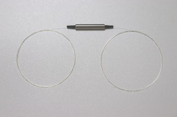
An OEM changing a source module from telecom operation to 1064 nm should reopen the mechanical drawing as well as the optical requirement. The nominal housing can look familiar while its fiber, loss and environmental limits change. HI1060 is the stated fiber for this unit; a familiar SMF-28e designation from the telecom assembly is not a reason to overwrite it. Identify the transition to the next fiber and establish where its loss will be measured.
For a source with a pulse specification, the listed 300 mW CW rating is not a pulse-energy or peak-power approval. Describe the actual illumination condition and request confirmation before installation. This matters even if a meter reports a low average value: that value alone does not describe the instantaneous condition at the isolator. No additional pulsed-power rating is assumed for this SM product.
Source-protection acceptance should preserve connector and environment conditions
The standard polarization-insensitive isolator says its specifications exclude connectors and adds 0.2 dB insertion loss when a connector is added. The 1064 nm SM entry gives a different connector allowance of 0.3 dB. Use the selected product’s condition rather than applying one universal allowance across all isolators. Clarify the delivered endpoints and whether the assembled test includes additional mating connections.
The standard unit lists 300 mW optical power and −5 to +70 °C operation. The 1064 nm SM unit also lists 300 mW CW, but with −5 to +50 °C operation. A lower transmitted power at the receiver does not establish the power entering the isolator. Confirm the source-side condition and temperature for the chosen variant, particularly when the design changes wavelength.
For the source module, measure forward loss and the required reverse route under defined wavelength and input-state conditions. Keep return loss separate from isolation: return loss concerns reflection at an interface, while isolation concerns unwanted reverse transmission. A favorable reflection result should not be used as proof of the reverse suppression the source needs.
PDL acceptance also needs a measurement that actually changes the input state. Repeating a forward-loss reading with the same source state can demonstrate repeatability in that setup, but it does not establish the stated polarization-dependent limit. For the standard unit’s 0.05 dB requirement, agree the state variation and instrument uncertainty used for acceptance. Otherwise a difference comparable to the instrument uncertainty can lead to an unjustified rejection or approval.
Keep the isolation sign and reference power clear in the test document. A reverse power ratio expressed in dB should identify the launched and received ends; it should not be recorded merely as a low detector reading. A detector below its measurement floor gives a bound rather than a precise high isolation value. Match that bound to the source’s minimum requirement before treating it as sufficient evidence for a single- or dual-stage selection.
When comparing sample records, retain which endpoint was the input and how the source state was established. A forward measurement under one condition and a reverse result under an unrelated condition cannot automatically describe the same installed use. Agree the conditions that matter to the source, then ask for evidence tied to that selected device. No actual test result is claimed here.
For shipment, request protection of the chosen connector faces and support that prevents loading the small isolator housing through its leads. Identify wavelength, stage and direction in the unit documents. A distributor handling similar cylinders should separate the mini, L-band and 1064 nm variants so the installation team does not select a mechanically convenient but spectrally unsuitable spare.
Feiyi’s fiber-isolator guide covers the broader protection context. Approve your SM route from its actual wavelength interval, minimum reverse requirement and connectorized forward budget. If the next optical element also needs a stable polarization reference, resolve that additional interface deliberately; the isolator’s polarization insensitivity should not be asked to perform a different job.