Stock Distinct Control and Wavelength Options With a Variable Optical Attenuator Supplier
A request for “a VOA, 1550 nm” is too short to identify a useful replacement. A service technician may need a hand-adjusted attenuator; an instrument designer may need an electrically controlled component; a polarization-sensitive laboratory may need a PM path. A variable optical attenuator supplier should separate those orders before comparing their attenuation ranges. Feiyi offers single-mode manual attenuation, MEMS VOA options and PM variants. Start with the adjustment method, operating wavelength and fiber requirement, then assign an order identity that preserves all three.
For a distributor, this separation prevents a familiar-looking package from becoming an unsuitable substitute. The figures below describe the named Feiyi families, not quantities held in stock. Availability, the exact configuration and delivery timing require order confirmation.
Three bins that should stay distinct: hand-adjusted SM instruments; controller-driven MEMS assemblies; PM paths with a defined axis. Wavelength and termination still subdivide each bin. An adjustment range alone cannot bridge these differences.
A variable optical attenuator supplier should identify how the buyer changes optical power
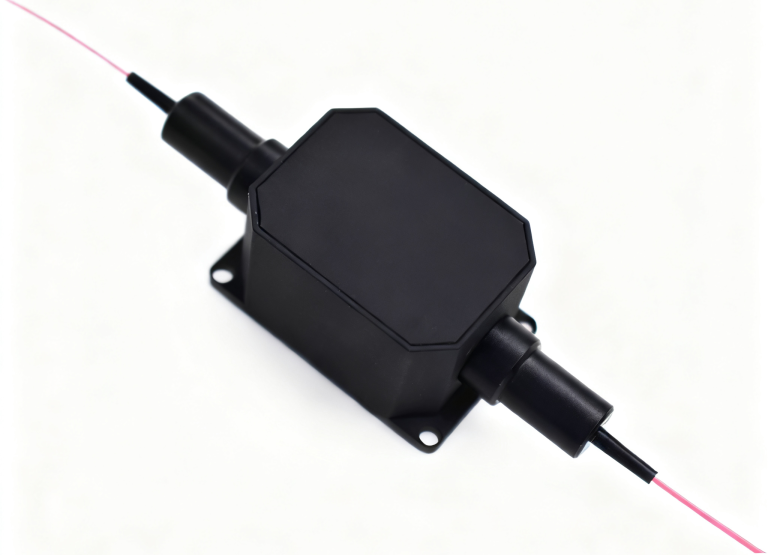
Feiyi’s single-mode fiber VOA lists a 26 × 18 × 8 mm package and an adjustment interface for manual power setting. Its wavelength columns cover 780/850 nm, 980/1064 nm and 1310/1550 nm. A technician assembling a repeatable component-test setup can use this family as a starting point when a person sets the attenuation and records the measurement conditions.
The separate online adjustable VOA lists 1550 nm grades, a 1310 nm option and a 1310–1630 nm broadband option. “Online” should not be interpreted as a software interface. Confirm the actual adjustment arrangement, mounting and required access. A buyer expecting a programmable connection should not receive a manual device simply because both descriptions say adjustable.
Manual SM VOA settings need wavelength-specific loss limits
The manual family’s 780/850 nm column lists attenuation from 1.0 to 60 dB and insertion loss no greater than 1.0 dB. Its 980/1064 and 1310/1550 columns list 0.8 to 60 dB and insertion loss no greater than 0.8 dB. The listed bands are ±20 nm for the first two groups and ±40 nm for the telecom group. Preserve the selected column when creating the distributor’s item description.
A low-power test may need attenuation close to the device’s minimum. A unit capable of reaching 60 dB is not necessarily suitable if the unattenuated route cannot tolerate its minimum loss. Establish the required low-loss setting before judging the upper range. The manual product’s maximum optical-power entry is 500 mW; a detector reading after attenuation is not the power entering the unit.
The Thorlabs attenuator technical overview explains attenuation as a separate controlled optical function. OZ Optics’ attenuator documentation similarly distinguishes configuration and measurement conditions. These references help frame the order; their performance values do not replace Feiyi’s selected specification.
MEMS VOA control belongs in an assembly-specific order
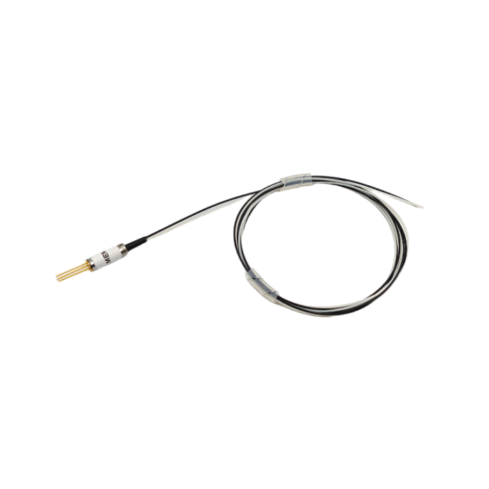
The Feiyi MEMS VOA lists bright and dark types, a minimum-loss limit of 0.7 dB, single-mode attenuation of at least 30 dB and a dark-type blocking figure of at least 40 dB. Its operating selections include 850/1064 nm, the 1310 nm O-band, 1530–1570 nm C-band and 1570–1610 nm L-band. Treat the selected band and power-off behavior as part of the supplied identity.
Bright and dark MEMS variants require a defined startup state
An instrument that protects a sensitive receiver during startup should state what attenuation is required before normal control begins. The bright/dark designation should be matched to a confirmed device response and wiring arrangement. Do not assume that a unit is fail-safe solely from a product name. Ask for its approved power-off and startup behavior under the selected drive conditions.
The MEMS listing contains inconsistent drive-voltage and operating-temperature entries between its specification and ordering information. An order should therefore refer to an approved revision identifying the actual drive range and environment. A distributor should avoid printing either disputed value on a generic stock label. Resolve it for the supplied model before giving an integration engineer a connection instruction.
The listed response time is no greater than 2 ms for the 10–90% optical-power transition. That condition does not describe an entire feedback system. A detector, controller sampling interval and control algorithm can add delay or alter the settling behavior. An OEM should establish when its power measurement may begin after a command, using the completed assembly rather than assuming the component transition figure is a complete settling guarantee.
A MEMS VOA electrical request needs its optical reference attached
A command voltage is only useful if its resulting attenuation has been established for the selected unit and wavelength. Define how calibration will relate the electrical input to transmitted optical power. If the source band changes, confirm whether the same command map remains acceptable. The distributor’s documentation should distinguish a bare optical component from a component supplied with an independently confirmed controller or calibration file.
The MEMS page lists 500 mW optical power and a 5.5 mm diameter by 17 mm package. Those entries should remain tied to this product family. They do not establish a safe electrical drive limit, a universal mounting tolerance or a PM extinction specification. A mechanically compatible replacement can still require a different controller setting or optical approval.
PM attenuation should occupy a separate polarization-controlled item family
Feiyi’s 1310/1550 nm PM VOA lists attenuation of 0.6–60 dB, insertion loss no greater than 0.6 dB, return loss of at least 50 dB and extinction ratio of at least 18 dB. Its optical-power limit is 300 mW. The same package dimension as a manual SM unit does not make the two interchangeable.
A separate 780 nm PM VOA lists a ±50 nm operating band, PM780HP fiber or specified alternatives, and a 300 mW maximum optical-power entry. A laboratory requesting a 780 nm PM attenuator should not receive an ordinary 850 nm SM item just because both operate near the same broad spectral region. Mode, axis and the approved band all matter.
The 780 nm PM order should preserve connector-axis orientation
For the PM family, the default connector key is aligned to the slow axis. Confirm the required orientation at both endpoints and preserve it in the item description. A replacement selected only by connector shell and wavelength can introduce the wrong polarization interface. If the laboratory’s instrument expects another orientation, obtain a confirmed custom arrangement rather than treating the default as universal.
The PM specifications exclude connectors; the listed connector allowance adds 0.3 dB insertion loss, reduces return loss by 5 dB and reduces extinction ratio by 2 dB. Agree whether acceptance is for the unconnectorized device or the supplied end-to-end assembly. These corrections should not be applied indiscriminately to the MEMS family, whose listed connector loss allowance is different.
The telecom PM VOA’s fiber entries need configuration confirmation because the table and ordering section do not identify the same wavelength-specific fiber consistently. Keep the chosen wavelength and PM requirement, but request the approved fiber designation. This is a purchasing issue that a part-number suffix alone cannot safely resolve.
Broadband online attenuation needs a different spare from a narrowband low-loss setting
The online adjustable family lists a 1550 nm P-grade attenuation range of 0.3–65 dB with typical insertion loss no greater than 0.3 dB. Its 1550 nm A-grade entry is 0.6–60 dB with typical insertion loss no greater than 0.6 dB. The broadband 1310–1630 nm option lists 1–60 dB with typical insertion loss no greater than 1 dB. Compare like conditions before describing one version as the lower-loss spare.
Consider a service organization measuring several telecom bands with one attenuation route. A confirmed broadband option can reduce the need to exchange wavelength-specific devices. A fixed 1550 nm bench setup may instead value the smaller listed minimum loss. Neither case establishes that the broadband and P-grade versions have identical behavior at every attenuation setting.
The online family states PDL no greater than 0.1 dB over 0–20 dB attenuation and no greater than 0.2 dB over 20–60 dB. Keep the attenuation interval with the PDL condition. A test performed at one low setting should not certify the higher range. Likewise, a nominal range ending at 65 dB should not automatically inherit a PDL limit explicitly stated only through 60 dB.
Replacement records should distinguish minimum loss from added attenuation
Tell the buyer how the attenuation scale is referenced. If the receiving test records total end-to-end loss, its lowest setting includes the assembly’s baseline insertion loss. If a controller reports attenuation relative to that baseline, the displayed number describes something different. Define the reference in the measurement record so a distributor does not compare unlike values and misclassify a replacement.
At high attenuation, detector sensitivity can limit the measurement. A low reading below the instrument floor gives a bound rather than an exact verified range endpoint. Agree the source stability, receiver range and connections for the actual variant. Avoid issuing a generic “60 dB passed” statement without identifying how that result was established.
A distributor receiving a manual 1310 nm unit can ask for results near its minimum setting and at the attenuation levels the customer actually uses. That request is more useful than testing only the deepest setting. If the customer later adopts a broadband online version, repeat the agreed comparison at the needed wavelengths. The replacement’s wider band should be demonstrated under the relevant conditions rather than inferred from the original narrowband record.
For PM samples, retain extinction information alongside transmitted power at the agreed settings. A favorable attenuation result does not by itself confirm axis preservation. If the assembly uses a different connector arrangement from the approved sample, review both the loss allowance and the extinction boundary. This keeps a replacement decision attached to the PM interface the laboratory uses.
Distributor handling should protect the adjustment interface and the ordered fiber ends
The manual SM family offers bare fiber, 900 µm loose tube and 2.0 or 3.0 mm jackets, with listed lead lengths including 0.5, 1, 1.5 and 2 m. These choices change how a service technician connects and supports the device. A bare-fiber unit intended for splicing should not be presented as a ready-to-connect replacement for an FC/APC instrument.
Request packing that protects the adjustment feature from unintended loading and isolates the chosen connector faces from contamination. For a MEMS component, identify the confirmed electrical interface without allowing exposed wiring to load the small cylindrical body. These are handling requirements to agree for the order; no particular factory packing method or delivery time is asserted here.
Feiyi’s optical power attenuation guide provides further context for the device’s job. Build a distributor item around the user’s adjustment method, wavelength, fiber and measured boundary. When a buyer changes any of these, reopen the configuration before offering a substitute, even if the replacement can reach the same upper attenuation number.