Give a PLC Splitter Manufacturer the Cabinet Termination Plan Before Selecting the Package
The optical split can be correct while the cabinet installation is wrong. A connector buried behind other leads, a module that blocks the service opening or an unlabeled output can make an access-network expansion unnecessarily difficult. Give your PLC splitter manufacturer the cabinet termination plan before choosing a package. Feiyi’s insert-type PLC splitter, ABS-box version and mini splitter provide different starting points. First confirm the output count, branch-loss allowance and how each lead or connector will remain accessible.
This decision concerns contractors building FTTx or PON distribution, equipment integrators and service teams adding branches to an existing cabinet. It is not enough to select the device with the most outputs. The splitter must fit the actual termination arrangement without using up the remaining optical budget.
A PLC splitter manufacturer needs the cabinet’s service arrangement
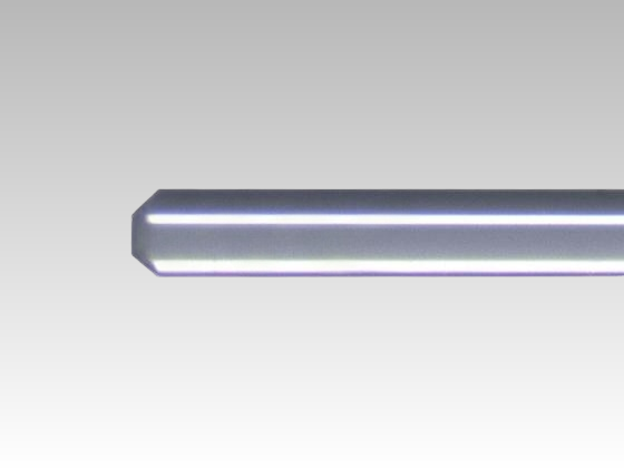
The insert-type product image shows a housing with front connections. That arrangement can be relevant when the service team needs access to a defined connector bank. Before ordering it, identify the mating adapter, connector finish, allowed protrusion and access needed to remove a connection. A front-facing arrangement is useful only if the installed cabinet allows the technician to reach it.
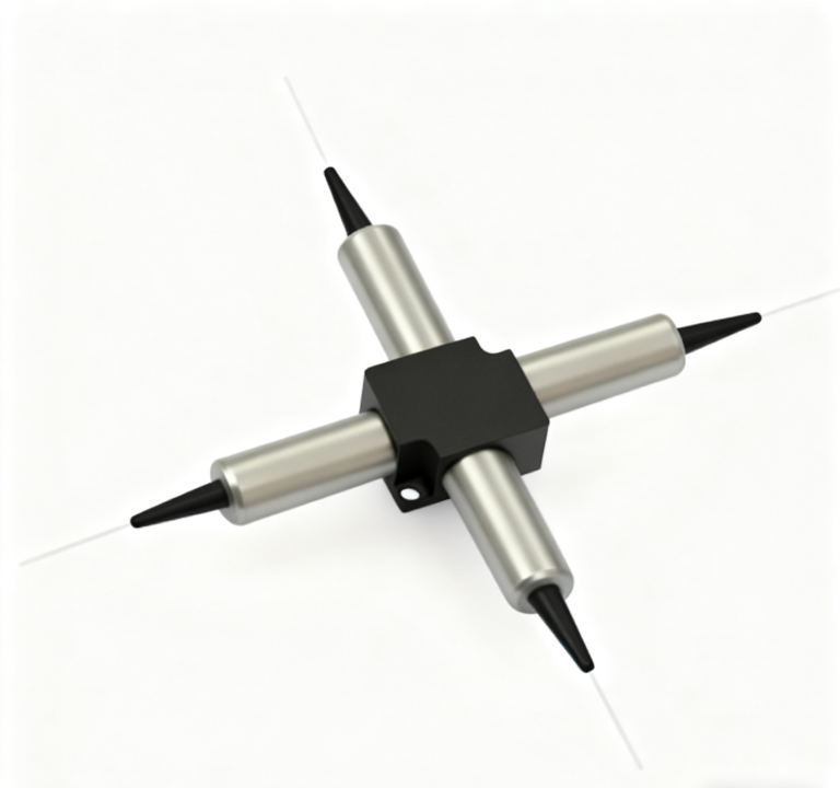
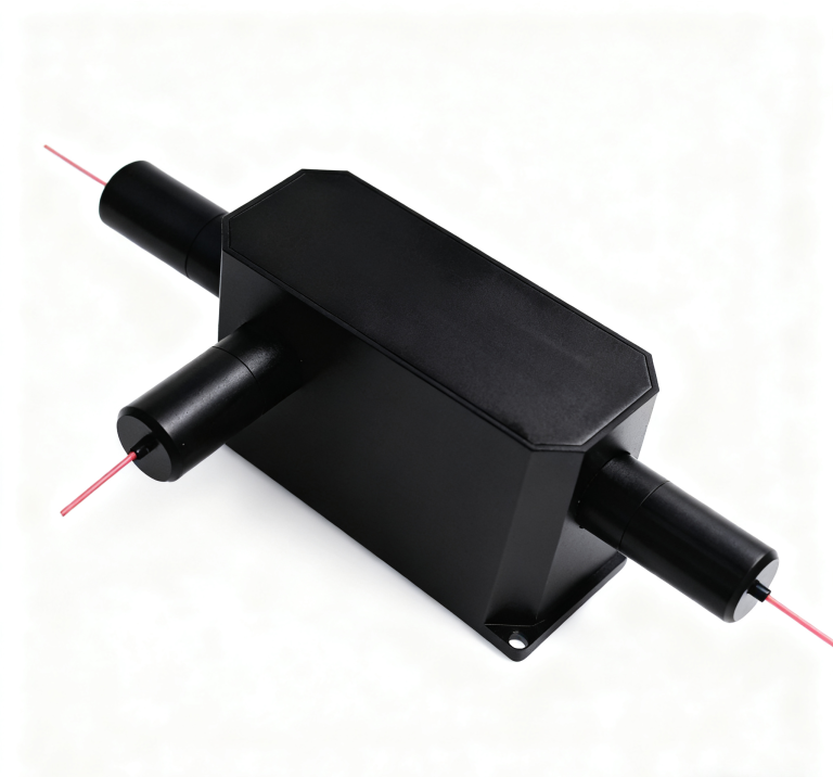
The ABS-box product presents a protected splitter assembly with outgoing leads. This is a different installation decision: the enclosure’s position and the route to external termination points need definition. The mini family provides another compact approach when an integrator manages the mounting and lead organization. These names do not establish universal compatibility with a customer’s existing frame.
Follow the installed branch: input termination → splitter mounting point → identified output lead → service connector. Approve the space and optical reference at each boundary. Package selection becomes clearer when the installer can trace this complete route.
Insert-type PLC connectors must remain removable after the cabinet is populated
Consider a contractor installing the splitter in an almost full distribution cabinet. A clean photograph before adjacent equipment is fitted does not prove that the connectors will remain serviceable. Use the real adapter position and lead routing to check access. Ask for the chosen insert’s dimensional drawing and the required retention arrangement; do not select it from the bare splitter chip’s dimensions.
Confirm whether the supplied unit includes the intended adapters or only a particular connector termination. The ordering information lists FC/PC, FC/APC, SC/PC and SC/APC options. Matching the shell alone does not match the polished interface. The ordered ends should agree with the receiving termination system, without forcing unlike finishes into a convenient connection.
The 1×16 versus 1×32 PLC decision changes every branch’s allowance
Feiyi’s 1×N table lists 1260–1650 nm operation and output counts from 1×2 through 1×128. At 1×16, the P/S-grade insertion-loss entries are 13.5/13.7 dB. At 1×32 they are 16.5/16.9 dB. A contractor moving to twice as many branches must therefore reopen the branch calculation rather than regard the larger count as a mechanically simple expansion.
For the listed P-grade entries, the increase from 1×16 to 1×32 is 3.0 dB. This is a comparison of two catalog limits, not a measurement of a specific delivered unit or a guarantee of network reach. Include the other installed components, fiber and termination losses under the system designer’s budget. A larger branch count may fit the cabinet while failing the required receiver condition.
Unused PLC outputs do not return their share to occupied branches
If a 1×32 splitter is installed with only sixteen active outputs, the active routes should still be evaluated as branches of the selected 1×32 device. Leaving outputs unused does not turn it into a 1×16 splitter with the lower listed branch loss. Choose future capacity deliberately and budget the selected optical split from the beginning.
For an expansion project, identify which outlets are assigned now and which remain reserved. Request a clear port schedule that distinguishes unused branches from disconnected active services. Preserve the splitter’s input identification. An installer should not have to infer the common lead from an unlabeled bundle after the module has been mounted.
P-grade and S-grade branch results should remain in their own column
At 1×8, the listed P/S insertion losses are 10.2/10.5 dB; at 1×64 they are 20.5/21.0 dB. The grade also accompanies return-loss entries of 55/50 dB. If the purchase specifies one grade, receiving documentation should identify that grade rather than borrow a favorable value from another column.
The table also gives loss uniformity of 1 dB for 1×16 and 1.5 dB for 1×32. Uniformity describes variation among output paths under the measurement conditions. It should not be used as the insertion loss of each branch. A low average loss can hide a branch that exceeds the agreed individual requirement, so retain per-output results for the ordered device.
For a 1×32 P-grade order, a per-output receiving sheet should identify all thirty-two intended paths rather than list only the outlets initially assigned to subscribers. Reserved outlets can become service paths later. Establishing their condition before installation reduces uncertainty when the network expands. If the installer connects only the first sixteen now, keep the remaining identities readable and protected instead of treating those leads as an anonymous spare bundle.
The 1×N table gives PDL of 0.24 dB at 1×16 and 0.3 dB at 1×32. A branch-loss result under a single input state does not independently establish that variation. Where the network acceptance requires it, agree the input-state method and conditions for the selected output count. Increasing the output count changes more than the number of terminations, so the final specification should retain the corresponding loss, uniformity and polarization conditions together.
The ABS box and mini splitter place lead management in different locations
An ABS assembly can keep the splitter in a defined enclosure while leads reach separate termination points. For an installation where those points are already fixed, provide their distances and routing constraints before choosing lead length. A surplus bundle should not be used to compensate for a package whose exit arrangement was never checked against the cabinet.

The mini and bare-device dimension tables list several different envelopes, while the module tables list larger assemblies. They should not be combined into a single universal mounting size. The same output count can appear in different package contexts. Ask for a drawing tied to the selected assembly, including exits and any separate termination hardware, before approving its mounting footprint.
G657A1 and 900 µm options do not eliminate fiber-routing limits
Feiyi identifies G657A1 fiber or a customer-specified alternative, and its ordering options include bare fiber and 900 µm loose tube. The stated fiber type does not make an arbitrary tight bend safe. Confirm the actual lead construction and its installation requirement. A drawing should show where leads are supported and where they transition to the cabinet’s termination system.
The order lists lead lengths such as 0.5, 1 and 2 m. Select enough length to reach the intended endpoint and allow the agreed service access, then identify how surplus length will be stored. A bare-fiber installation and a connectorized insert require different handling at the termination boundary; do not describe them as interchangeable simply because the internal optical split is the same.
Branch acceptance should be repeated at the wavelengths the access network uses
The 1260–1650 nm operating range supports consideration across multiple access-network wavelengths, but the receiving test should identify the actual operating wavelengths and conditions needed by the network. A single result at a convenient test wavelength does not prove every spectral requirement. Agree the points or interval that the operator needs and retain the port identity with each reading.
The PLC table gives wavelength-dependent loss of 0.5 dB for the 1×16 and 1×32 entries. Keep this as a separate condition from the insertion-loss and uniformity limits. If the branch test is repeated at several wavelengths, record which variation is being compared. Otherwise, an apparent branch difference may reflect a change in wavelength rather than a port-to-port condition.
Corning’s PLC splitter overview describes the general access-network distribution function. Its splitter installation instructions illustrate why handling and termination belong in an installation plan. Specific assembly procedures and performance figures from another manufacturer’s module do not become instructions for Feiyi’s product.
A connectorized PLC receiving test needs defined endpoints
Specify whether the test begins at the splitter’s supplied input connector and ends at each supplied output connector, or measures a different device boundary. Mating adapters, test leads and reference connections should be identified. A test of an unfinished splitter is not automatically an end-to-end test of the final connectorized assembly.
Inspect and clean the intended connection before interpreting an abnormal branch-loss reading. If one route differs, isolate its connection condition before blaming the entire splitter. Record the port number and the test reference so that a repeated reading can investigate the same path. Do not replace an individual-port requirement with an average over the assembled outputs.
PLC distribution and fused taps answer different cabinet needs
A cabinet that distributes optical power to many nominally equal branches can begin with the PLC family. A monitoring arrangement that preserves most power on one route and taps a smaller share may instead examine Feiyi’s single-mode fused coupler. Its unequal-ratio choices should not be treated as a way to obtain the PLC’s multiple equal output branches.
A service team adding only a monitoring connection should first identify the desired tap fraction and spectral condition, then decide whether a separate tap is appropriate. A contractor adding subscriber branches should identify their count and branch budget. These tasks can occur in the same cabinet, but their optical decisions differ.
The PLC 1×N entries list operation from −40 to +85 °C. That component range does not establish an outdoor cabinet’s ingress protection or an entire connectorized installation’s environmental certification. Describe the installation environment and request confirmation for the supplied package. Protect exposed terminations according to the actual enclosure arrangement, rather than assuming that an ABS product name establishes a sealed installation.
For delivery, request output identification that remains usable while the leads are coiled for transport and then separated for installation. The connectorized ABS assembly needs protected faces and supported lead exits; the insert needs its interface protected from handling damage. These requirements should be agreed for the selected assembly, without inventing a standard packing method.
Feiyi’s insert-type splitter explanation gives more context for this approach. Approve the unit when the contractor can trace each intended branch, reach its termination and demonstrate its optical allowance. That is a stronger installation decision than selecting the largest output count that fits an empty space.