Plan a Network Node’s Loss Budget With a Passive Fiber Optic Components Supplier
An optical network node can fail its receiver budget even when every passive part meets its own specification. The mistake is often choosing a splitter, wavelength module and connector system separately, then discovering their combined loss after installation. A passive fiber optic components supplier is most useful when the order follows the actual light path. Feiyi’s mini PLC splitter, single-mode fused coupler and 8-channel CWDM mux/demux serve different jobs. First decide whether the node distributes one signal, taps a small fraction or separates wavelengths.
For an access integrator, that distinction comes before selecting a box size. A many-output splitter cannot be replaced by an eight-channel wavelength module merely because both have multiple fiber connections. Likewise, a monitoring tap should not consume half the traffic power unless the network was designed for that split. Establish the feeder, subscriber and monitoring routes before allocating component loss.
A passive fiber optic components supplier needs the node’s branch diagram
Imagine an access node receiving several wavelengths on one feeder and distributing a selected service to subscriber fibers. A CWDM demultiplexer first routes the selected wavelength to its corresponding port. A PLC splitter then distributes that signal among branches. Only the components actually traversed by a particular receiver belong in that receiver’s loss budget. Counting unused wavelength ports as serial devices would be as misleading as forgetting the splitter.
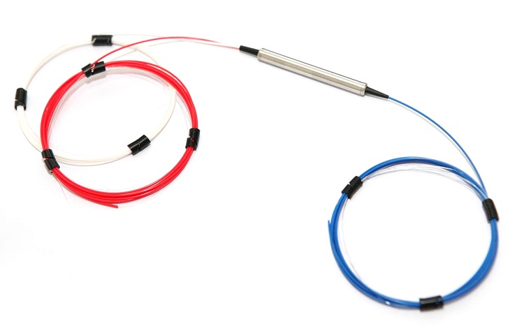
Feiyi’s mini PLC range lists 1×2 through 1×128 configurations and an operating band of 1260–1650 nm. The 1×8 entry lists insertion loss of 10.2/10.5 dB for P/S grades; the 1×16 entry lists 13.5/13.7 dB. Moving from eight to sixteen outputs therefore requires a new budget, not just additional connector space. Preserve the grade and number of outputs when discussing the requirement.
A 1×8 PLC branch carries splitting loss even when seven outputs are unused
An integrator installing only three subscriber connections may be tempted to budget the device as a three-way split. The selected 1×8 PLC still distributes optical power across its eight outputs. The unused ports do not return their share to the three active subscribers. Select a smaller splitter if expansion is unnecessary, or reserve sufficient margin for the larger installed device from the start.
The Feiyi mini PLC specifies G657A1 fiber or a customer-specified alternative. That is useful when routing fibers through a compact termination, but it does not remove connector loss, splice loss or the need for proper lead support. The device and module dimension tables contain different package arrangements. Identify the exact enclosure and outgoing fiber style instead of treating every listed 1×8 unit as mechanically identical.
Passive component loss should be allocated per optical path
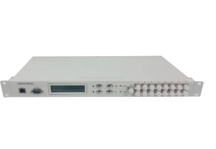
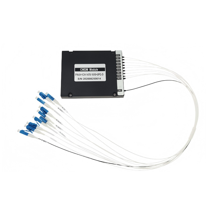
Use a separate row for each traversed device. Feiyi’s 8-channel CWDM module lists an 8-channel insertion-loss limit of 2.5 dB, while its four-channel entry lists 1.5 dB. If a signal passes through both an eight-channel multiplexer and an eight-channel demultiplexer, budget both units. A favorable value for one channel at one end does not justify counting only half of the wavelength-routing path.
| Traversed element | Value used in this example | Meaning for the design |
|---|---|---|
| Eight-channel CWDM at the transmitting end | 2.5 dB | One wavelength-routing device |
| Eight-channel CWDM at the receiving node | 2.5 dB | A second routing device, counted separately |
| 1×8 PLC, P-grade entry | 10.2 dB | The selected subscriber branch |
| Subtotal before other losses | 15.2 dB | Fiber, connections, splices and reserve remain to be added |
This arithmetic deliberately stops before declaring a reach or a passing receiver level. The transmitter output, receiver sensitivity, fiber attenuation, connector population and required engineering reserve are not supplied by the component table. The connector inclusion condition also needs confirmation on the approved module specification. The subtotal is a way to expose the optical allocation, not a warranty that this combination supports your network.
Channel isolation does not reimburse insertion loss
The CWDM module lists adjacent-channel isolation of at least 30 dB and non-adjacent isolation of at least 40 dB. Isolation addresses unwanted wavelength leakage. Insertion loss addresses attenuation on the intended channel. Both matter, but improving one does not cancel the other. For an installation with strong and weak channels sharing a feeder, check leakage conditions as well as the desired signal’s received power.
Isolation and loss need separate route records. Build a second budget when the node has a different upstream path: a signal entering another wavelength port, bypassing the PLC or traversing another connector panel has a different component subtotal. Do not reuse the subscriber calculation for a monitoring receiver simply because both terminate in the same cabinet. Mark direction as well. Bidirectional operation requires a deliberate wavelength and port arrangement rather than an assumed reversal of every installed module.
Its 20 nm channel spacing and nominal wavelength alternatives of 1270–1610 or 1271–1611 nm should be tied to an explicit wavelength list. ITU-T G.694.2 defines the CWDM grid and its 20 nm spacing. Agree the actual nominal channels on both ends; do not approve a replacement from the broad wavelength range alone.
A fused monitoring tap preserves a different branch priority
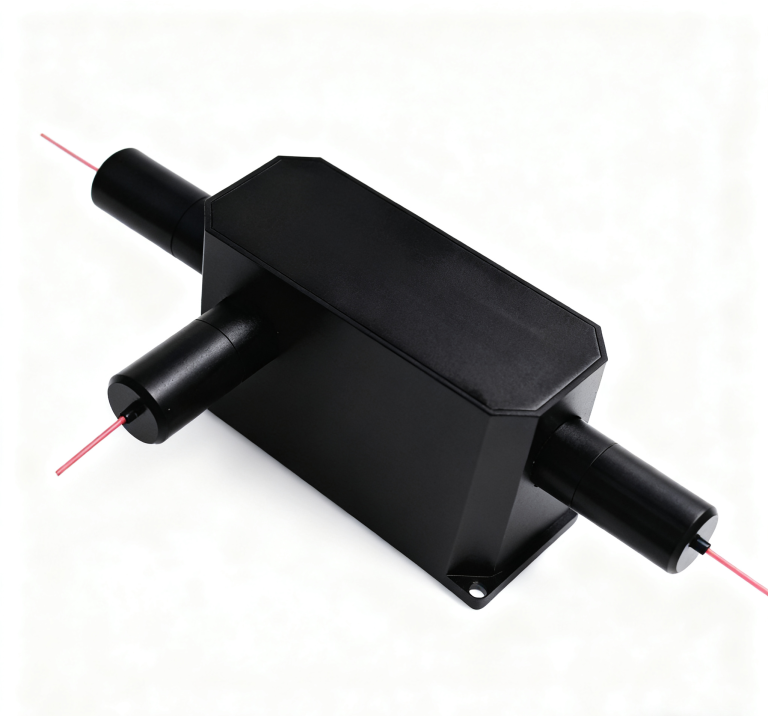
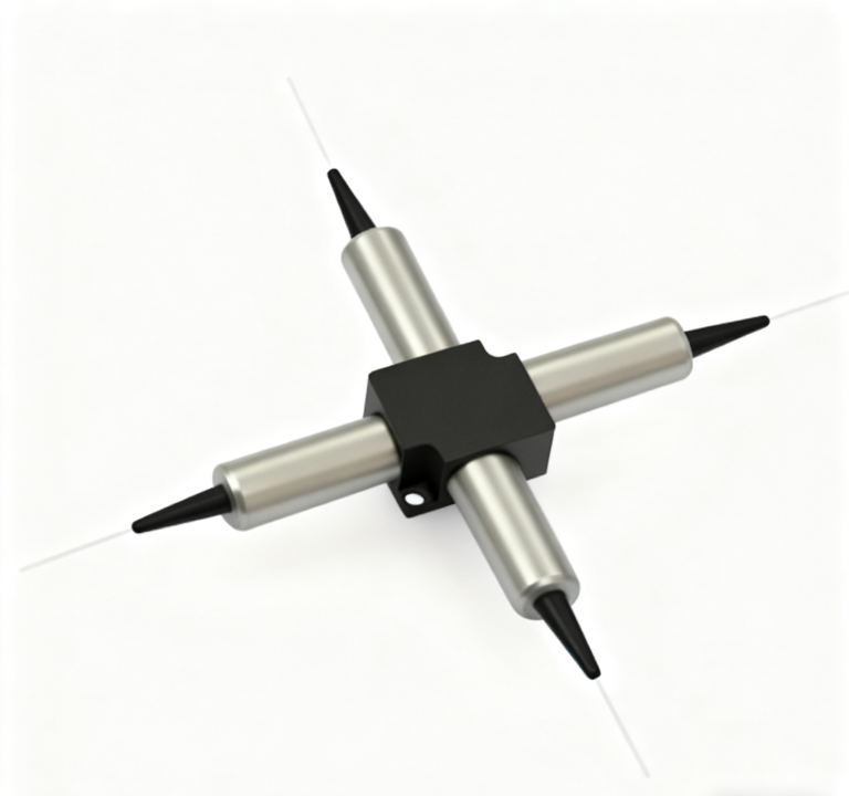
A maintenance team adding an optical monitor normally wants to preserve most traffic power on the through route. Feiyi’s single-mode coupler lists coupling ratios from 1% to 50%, with a 10/90 P-grade chart showing 10.8 dB on the tap branch and 0.6 dB on the stronger branch. Those are branch-specific entries. Applying the small through loss to the monitor detector would badly overestimate the available monitored signal.
For a hypothetical field-monitoring node, choose the tap fraction from both constraints: how much loss the traffic route can tolerate and how much power the monitor needs. A one-percent tap might protect traffic better, but its weaker branch requires a suitable measurement receiver. A larger tap may help the monitor while consuming margin needed by downstream subscribers. Neither route can be approved from “low excess loss” alone.
The operating window and branch behavior are separate choices. Keep an equal-split PLC’s branch comparison separate from the unequal tap’s comparison. Feiyi lists 0.8 dB loss uniformity for the 1×8 PLC and 1 dB for the 1×16 version. Uniformity does not replace the insertion-loss limit of each output: equally weak branches can still be unacceptable. Conversely, a 10/90 fused tap deliberately has different branch powers. Calling that expected difference a uniformity failure would apply the PLC’s job to the wrong component.
1310, 1480 and 1550 nm coupler versions need their own operating window
The Feiyi single-mode coupler lists 1310, 1480 and 1550 nm operating options, with custom wavelengths offered for discussion. It also distinguishes standard and wideband coupler entries. A 1550 nm tap in a mixed-wavelength feeder needs a confirmed working band and branch ratio at the wavelengths actually used. The fact that the fiber itself carries another wavelength does not prove that the coupler maintains the intended split there.
Thorlabs’ fused-coupler explanation distinguishes branch insertion loss from excess loss. That distinction helps interpret a supplier’s chart: the deliberate division of power is part of a branch’s insertion loss, while excess loss concerns additional loss beyond ideal division. Keep those terms separate when reviewing a tap instead of subtracting an ideal split twice.
DWDM and MPO choices change the node interfaces as well as the component list
Feiyi’s DWDM module in an LGX box is an alternative when the network uses the corresponding ITU-grid wavelength channels. It lists 100 or 200 GHz spacing, rather than CWDM’s 20 nm spacing. The four- and eight-channel insertion-loss entries are 1.8 and 3.0 dB respectively. Replacing CWDM with DWDM therefore changes the channel definition, compatible optical sources and loss allocation, not simply the module name.
The LGX ordering options include specific box and rack arrangements, connector choices and 900 µm, 2.0 mm or 3.0 mm cable styles. For a node installed in an existing cabinet, trace where those leads terminate and how much service loop is available. An optically suitable wavelength module can still be unsuitable if its exits or adapters collide with the termination hardware.
MPO ferrule grade belongs in the connector allowance
The MPO/MTP optical patch-cord entry distinguishes standard and low-loss ferrules, single-mode and multimode versions, and PC or APC finishes where applicable. Its standard single-mode typical insertion loss is 0.50 dB, with a maximum entry of 0.70 dB; the low-loss single-mode entries are 0.30 and 0.50 dB. Preserve the selected class and applicable test condition when allocating connector loss.
A purchaser should also identify male or female interfaces and the actual fiber-position map. More fibers in one connector do not automatically provide a compatible parallel-optics link. US Conec’s MTP information identifies MTP as a particular connector family within the MPO interface context. It does not mean every generic MPO assembly has that connector’s construction or that any channel arrangement supports a given transceiver.
Keep PLC output identification, CWDM channel labels and MPO fiber positions distinct on the receiving documents. A subscriber branch number is not a wavelength, and a connector fiber position is not automatically a subscriber number. Packaging labels should let the installation team match each unit to the agreed diagram without unfolding every lead or using an active network as an identification tool.
At acceptance, measure the selected PLC branches, the relevant wavelength paths and the assembled connector routes against their own limits. Preserve which losses include the termination and which do not. For an expanded access node, recheck the longest or weakest intended route rather than relying only on the easiest bench connection.
A distributor supplying a replacement node should preserve the selected optical allocation in its order description. An eight-channel CWDM box with another wavelength set is not a like-for-like replacement; a 1×16 PLC cannot be entered under the loss allowance for 1×8. Keep spare identifiers tied to channel set and branch count, so a field team does not select a physically convenient module that changes the subscriber power budget.
For the fused tap, request that the high-power through branch and weak monitoring branch remain unambiguously labeled after unpacking. For the PLC, retain each output identifier. For the wavelength box, keep nominal channel markings readable at the installed connector side. These details prevent a node with acceptable optical components from being wired into the wrong route, which no amount of extra numerical budget can correct.
Feiyi’s FTTH passive-component portfolio gives further context for access-network combinations. Approve your node from its branch drawing and budget, with the exact PLC count, tap ratio, channel set and connector class attached. If the reserve disappears, change the component doing the wrong optical job before searching for a vaguely “lower-loss” version of the entire bill of materials.