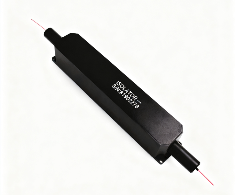
Choose a Mechanical Fiber Optic Switch Supplier for the Installed Route You Must Preserve
A replacement optical switch can fit the cabinet and still change where the signal goes when its drive is removed. Before selecting a mechanical fiber optic switch supplier, record the installed topology, unpowered behavior, drive voltage and fiber mode. Feiyi’s FY-FSW-1×2 mechanical switch offers latching and non-latching options, while its full 2×2 optical switch serves a different route arrangement. Start from the connection you must preserve rather than choosing by housing size or a general switch label.
This guide is for a service engineer replacing a routing element in an optical network cabinet, test fixture or monitoring assembly. The immediate priority is to retain the installed behavior without introducing an unintended bypass or disconnected receiver. A new device’s published low-loss figure is useful only after its ports and selected states match the existing job.
A mechanical fiber optic switch supplier needs the installed state drawing
Photograph and identify the optical ports before removing the original unit. Record which source reaches which receiver in each required state, including the condition with electrical drive absent. For a 1×2 replacement, define the common input and two destinations. For a full 2×2 replacement, define both simultaneous pairings. The route drawing should remain understandable without relying on the old unit’s wire colors.
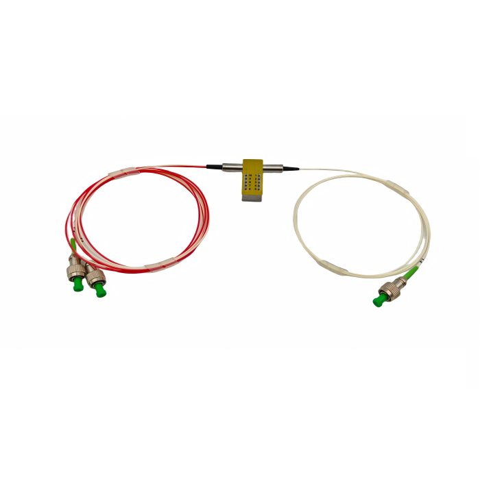
Feiyi’s FY-FSW-1×2 entry lists 3.0 or 5.0 V supply options and latching or non-latching control types. A latching selection and a non-latching selection are not interchangeable merely because both can reach the same two optical destinations while driven. Agree the selected construction and its approved drive requirements before connecting the replacement to an existing controller.
A 1×1 light gate is not a two-destination selector
The FY-FSW-1×1 switch is a candidate when the installed function opens or closes one optical path. A 1×2 routes one common path toward two destinations. If the cabinet uses the second destination as a service or monitoring route, replacing it with a simple light gate would remove that function. Confirm the required optical states before asking whether a smaller unit can fit.
The 1×1 entry lists typical insertion loss of 0.5 dB, maximum 0.8 dB and switching time no greater than 8 ms. Those values belong to that topology and selected conditions. They do not establish the limit for an arbitrary 1×2, 1×4 or paired-channel switch. Use the actual model identity when carrying performance information into the service order.
Mechanical optical switch replacements must retain the controller’s electrical contract
The installed controller may have been designed for a particular voltage, drive method and status-sensor interpretation. Feiyi publishes pin and state information for its mechanical families, but the service team should use the approved drawing for the exact supplied version. Do not copy one product’s pin arrangement to another family because its package appears similar. State feedback and optical routing must describe the same selected unit.
In a network cabinet, a switch that selects the backup path while energized may return to a different route when power is removed. A latching device may preserve its selected state. The application must decide which behavior is required. Choosing latching merely because retention sounds desirable can be wrong when the installation expects a defined return condition.
Full 2×2 and D1×2 switches have different simultaneous routes
The Feiyi full 2×2 entry describes alternative pairings such as P1-to-P4 with P2-to-P3 and P1-to-P3 with P2-to-P4. The FY-D1×2 mechanical switch instead describes paired route states with primed destination labels. Preserve the original port mapping when evaluating these families. Equal total lead counts do not prove that their optical states are equivalent.
For the full 2×2 SM entry, Feiyi lists typical insertion loss of 0.6 dB and maximum 0.8 dB, excluding connectors. The D1×2 entry lists 1.0 dB typical and 1.5 dB maximum, also excluding connectors. A proposed topology change therefore needs both a route review and a loss-budget review. Do not retain the old full-2×2 loss allowance when selecting a different paired arrangement.
A 1×4 route expansion is a redesign rather than a like-for-like replacement
Feiyi’s 1×4 T-type mechanical switch is relevant when the instrument needs a common path selected among four destinations. Its listed housing is 27 ×23 ×8.2 mm, larger across one dimension than the 27 ×12 ×8.2 mm 1×2 entry. A spare that replaces two destinations with four needs controller-state and mounting review, not only a more generous connector allowance.
The 1×4 entry lists switching time of 4 ms typical and 10 ms maximum. The 1×2 entry lists no greater than 8 ms. Use the selected family’s timing condition rather than applying the shortest number to every channel arrangement. The measurement or protection system should establish when it is safe to use the newly selected optical route, including any further system settling requirement.
Channel expansion changes lead identification and service access
A test-fixture operator replacing a two-output selector with four outputs needs a new common-to-destination map. Identify all four destinations before closing the enclosure. Preserve the unused-output identification as well, so an expansion later does not depend on tracing unlabeled fibers through the cabinet. The selected fiber exit and service-loop arrangement should fit the new package without pulling on its leads.
The 1×4 product lists SM or MM fiber, 3 or 5 V operation and connector choices. Those are separate selections. A wider channel count does not authorize a change from SM to MM or from one connector finish to another. Keep the installed optical interface stable unless the project explicitly approves the accompanying redesign.
The D2×2B bypass decision depends on the complete path diagram
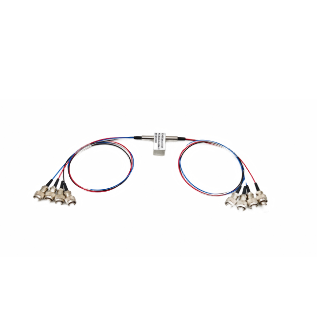
The FY-D2×2B mechanical switch lists one state with P1-to-P3′ and P2-to-P4′, and another arrangement containing additional primed path pairings. When replacing a bypass element, carry the full required diagram into the selection. A abbreviated “dual 2×2” label is not enough to establish which through and alternate paths stay connected.
Its listed wavelength combinations include 850/1300 nm for the corresponding MM arrangement and 1310/1550 nm for the corresponding SM arrangement. The entry gives a maximum insertion loss of 1.5 dB, excludes connectors and identifies the operating conditions. Define the actual wavelength and mode used in the cabinet so the replacement is accepted against the applicable configuration.
Low PDL does not turn an SM mechanical switch into a PM replacement
The ordinary mechanical entries list polarization-dependent loss limits. PDL describes how loss changes with input state; it is not a PM-axis preservation specification. If the installed device is part of a polarization-sensitive system, identify that additional requirement before selecting an ordinary SM replacement. The source or receiver may need a different documented PM switch family rather than this service guide’s standard SM/MM options.
The distinction also matters when a technician sees 9/125 fiber in the order options. That size is not proof of PM construction. Preserve the selected fiber designation and functional requirement. Feiyi’s comparison of magneto-optic and mechanical switches provides context for technology choices, but the installed route still needs its specific replacement approval.
Check the replaced switch with the cabinet’s actual optical boundaries
Begin with a controlled optical test of every required state and the approved status indication. Verify destination identity before relying on a receiver reading as proof of the correct route. Then measure the selected path loss with the connectors that the service replacement actually uses. A bare-device limit and a connectorized installed-path result should not be compared without their reference conditions.
The 1×2 and paired mechanical entries list repeatability of ±0.02 dB and lifetime entries of at least ten million cycles. Treat those as published specification entries for the supplied design. They are not evidence of the remaining service life of an old switch, nor proof that an installed cabinet has completed a reliability test. A replacement decision should use the actual fault history and required operating conditions.
Compare temperature requirements by model. The 1×2 entry lists −20 to +80 °C, the full 2×2 entry −20 to +70 °C and the 1×4 entry −5 to +70 °C. A topology change can therefore narrow the applicable environmental interval. Do not use the old switch’s temperature limit to approve the new family automatically.
The replacement switch’s 500 mW entry applies at its optical input
The ordinary mechanical entries list an optical-power limit of 500 mW, with the selected 1×4 entry expressed as less than 500 mW. Confirm the applicable rating for the exact supplied model. A service receiver reading little power does not show how much arrives at the switch before attenuation. Trace the source route and any combined power that can reach the selected input, including the service condition that originally caused the fault.
For an SM/MM replacement, preserve the intended fiber class and size. The ordering options include 50/125, 62.5/125 and 9/125 choices. A connector that physically mates can still join a different optical fiber class from the installed route. The replacement description should name the chosen option and wavelength instead of accepting a boot color as evidence. This avoids turning a routing repair into an unplanned fiber-interface change.
If the original fault appears only after cabinet movement, examine how the switch housing and leads are supported before ordering a different topology. The 1×2 housing and D2×2B housing have similar dimensional entries but different lead arrangements. A retention method that works for one should not be copied without checking the other exits. Preserve the optical route while correcting the actual mechanical support that the replacement requires.
On the completed service record, keep the installed model, selected latch type, voltage and verified route map together. Include the actual connected ends rather than a generic switch-family name. That lets a future engineer select the correct spare without reverse-engineering the controller or assuming that every 3 V mechanical unit has the same state behavior. The record is useful because it identifies this cabinet’s selected optical function.
Keep the 1×4 expansion drawing separate from the original 1×2 service record. Additional destinations create a new installed configuration; future replacements should reference that approved four-channel map, not the earlier two-route cabinet sketch.
Agiltron’s mechanical full-2×2 explanation provides background on selected-route switching and latching. Sercalo’s MEMS documentation shows another switching technology with its own drive and state behavior. Their timing, dimensions and qualifications should not be applied to Feiyi’s selected mechanical unit.
Agree shipping protection around the chosen housing and fiber exits, and preserve the port labels used by the service drawing. Keep the removed device identified until the replacement route has been verified, so an unexpected behavior can be compared with the original installation record. Release the cabinet when the intended states, power-loss behavior and receiver paths match that record; a mechanically convenient switch is not enough.