
PM VOA Manufacturer: Qualify the Attenuation Range You Actually Use
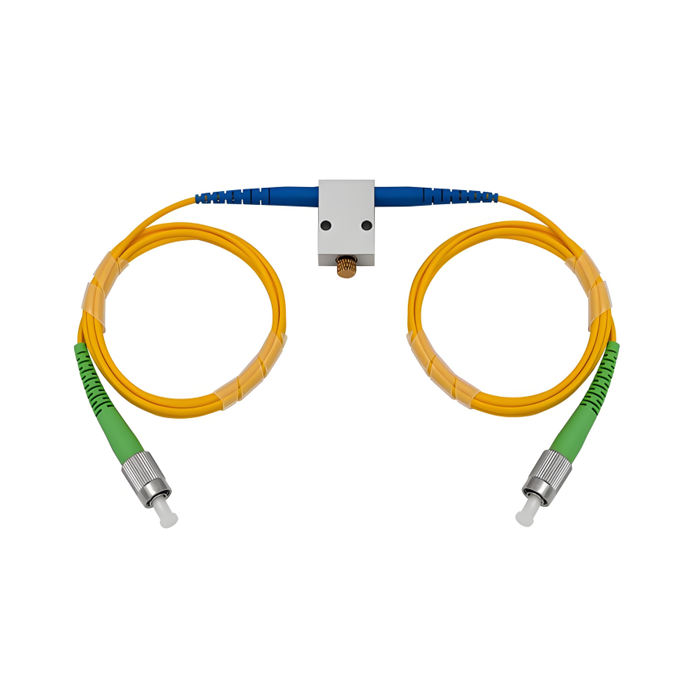
An engineer evaluating a PM VOA manufacturer should not begin with the largest attenuation number on a datasheet. The useful question is narrower: what optical power range must the receiver, sensor, amplifier, or test bench control while preserving the polarization state that the rest of the system depends on? Feiyi’s Polarization-Maintaining In-Line Variable Optical Attenuator publishes a 0.6–60 dB attenuation range, insertion loss of no more than 0.6 dB, return loss of at least 50 dB, and extinction ratio of at least 18 dB. Those figures are meaningful only when they are read together with wavelength, connector, axis convention, and the power level used in the real instrument.
Feiyi also lists wavelength-specific PM VOA products at 780, 850, 980, 1064, 1310, 1550, and 2000 nm. That product family gives buyers a practical starting point for laser systems, fiber sensing, optical communications, instrumentation, and EDFA power control. The purchasing task is therefore not simply to ask whether a supplier can provide a PM attenuator. It is to freeze the wavelength family, the usable attenuation window, the interface, and the acceptance method so a prototype can be repeated.
A PM VOA manufacturer should be judged across the attenuation range you will actually use
A variable attenuator is installed because an optical system needs controlled power, not because it needs the highest possible attenuation. If a detector is normally operated between, for example, two internal power limits, the engineering team should identify the attenuation settings that keep the detector inside that window. The useful part of the VOA range is the part that the instrument will repeatedly visit.
Maximum attenuation is not the same as useful control range
Feiyi’s in-line PM VOA page publishes a continuous attenuation range of 0.6 to 60 dB. A buyer should still ask how the unit will be used in the system. A sensing instrument may spend most of its life in a moderate attenuation region as source power or returned signal changes. A laboratory test setup may deliberately sweep much farther to evaluate receiver dynamic range. Those two applications can use the same product family while requiring different acceptance points.
For a production drawing, it is better to record several verification points within the actual operating region than to write only “0–60 dB.” That keeps incoming inspection focused on the settings that matter to the instrument. It also prevents a later replacement from being accepted simply because it reaches the endpoint while behaving differently where the system normally operates.
Insertion loss sets the zero-attenuation penalty of the power-control stage
Every passive component consumes some optical budget even before deliberate attenuation is added. The Feiyi PM in-line VOA specifies insertion loss of no more than 0.6 dB for the published base configuration. In a chain containing a PM isolator, WDM, circulator, patch cord, and VOA, that baseline loss must be included before the adjustable attenuation is used.
A buyer designing an EDFA or sensor bench can therefore separate two questions: how much fixed loss does the VOA add at its lowest setting, and how much additional attenuation is needed during operation? Treating those as different numbers makes the system budget easier to audit when another component or connector is changed.
PM VOA manufacturer selection changes with wavelength, even when the housing looks similar
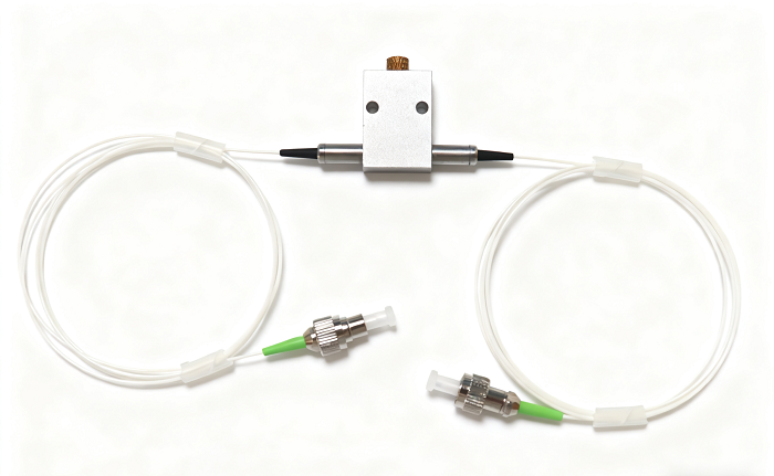
Feiyi’s product range includes several wavelength-specific PM VOAs. Their external appearance can be similar, but that does not make them interchangeable. The surrounding PM fiber, source, detector, connector convention, and system loss budget are wavelength-specific. Procurement should keep those variants as separate approved line items.
| Feiyi PM VOA option | Where the buyer starts | What must stay tied to the order |
|---|---|---|
| 780 nm PM In-Line VOA | Shorter-wavelength PM laser or sensing platform | Wavelength, PM fiber, connector, axis convention |
| PM 980 nm VOA | 980 nm source or amplifier-related optical path | Power range, connectorization, repeat settings |
| PM 1064 nm VOA | 1064 nm laser or precision photonics assembly | Source wavelength, polarization state, optical budget |
| PM 1550 nm VOA | 1550 nm communications, sensing, or test system | Attenuation window and mating interface |
| PM 2000 nm VOA | Longer-wavelength PM platform | Approved fiber and complete optical interface |
A multi-wavelength laboratory should keep separate approved builds
A laboratory may own 980 nm, 1064 nm, and 1550 nm instruments that all need variable power control. It is tempting to describe the spare part as “PM VOA, FC/APC” because the housings and connectors look alike. That description is not sufficient. The approved wavelength family, fiber type, axis convention, and measured acceptance points should remain visible on each internal part record.
The same discipline helps distributors. Stock can be physically separated by wavelength and labeled with the exact Feiyi product family rather than by appearance. This reduces the risk of supplying a mechanically compatible unit that is optically wrong for the customer’s source.
Connectorized PM VOA performance should be read differently from bare-fiber data
Feiyi’s PM in-line VOA page makes an unusually useful distinction: the published table notes that the base data do not include connectors. It states that adding connectors increases insertion loss by 0.3 dB, lowers return loss by 5 dB, and lowers extinction ratio by 2 dB. Those are site-published product notes, not generic assumptions, and they should be reflected in the acceptance target for a connectorized order.
FC/APC may solve an interface problem while changing the measured component budget
The generic PM in-line VOA page lists FC/APC or other connector options. An APC interface can be appropriate when the surrounding instrument is designed around angled physical-contact connectors and reflected power at the interface is a concern. But the system engineer should not compare a connectorized production unit directly with a bare-fiber table without accounting for the published connector effect.
For a buyer replacing an existing VOA, the mating adapter and neighboring patch cord should be identified before the order is released. A connector change can alter more than convenience: it changes the optical interface, and it can invalidate a baseline loss or extinction-ratio limit copied from a bare-fiber prototype.
The connector key is also a polarization reference
The Feiyi PM VOA page states that, by default, the slow axis of the fiber is aligned with the connector key. That is a critical assembly detail in a PM system. A keyed connector lets the technician reproduce a rotational relationship, but only if both sides of the connection use the same convention.
If a sensor or instrument was built around slow-axis alignment, purchasing should preserve that definition on the drawing. If a special build uses a different axis convention, the deviation should be explicit rather than left to an installer to discover from poor extinction ratio after assembly.
PM VOA manufacturing acceptance should reproduce both power and polarization conditions
Incoming inspection is most useful when it resembles the optical state the product will see in service. Measuring only end-to-end power with an uncontrolled launch can miss a polarization problem. Conversely, measuring extinction ratio without checking the attenuation settings used by the instrument does not confirm the power-control function.
A fiber-sensing instrument should test the VOA with the same axis convention as the sensor chain
In a fiber sensor, a PM patch cord, isolator, circulator, or coupler can sit next to the VOA. If one connector is rotated or one component uses a different axis definition, the complete chain can lose polarization performance even though each device passed a separate test. The acceptance setup should therefore use the same key orientation and PM launch convention as the installed sensor.
Feiyi publishes return loss of at least 50 dB and extinction ratio of at least 18 dB for the base PM in-line VOA. Those values provide a reference for the product itself. The project can then add its own system-level acceptance limit without pretending that one component alone determines the polarization behavior of the entire assembly.
An EDFA power-control bench may care more about repeatable settings than the 60 dB endpoint
The Feiyi page names EDFA power control as one application. In that context, the VOA may be used to place optical power at several known levels during setup, characterization, or operation. If the bench repeatedly uses the same few settings, those points deserve attention during sample approval and replacement testing.
The buyer can record the source wavelength, launched power, measurement instrument, and selected attenuation points. This creates a practical comparison between samples without claiming a precision or resolution that the Feiyi page does not publish. It also keeps the purchase specification tied to the way the VOA is actually used.
A PM VOA manufacturer should receive the operating power envelope before the connector list
The Feiyi PM in-line VOA page publishes maximum optical power of 300 mW, an operating temperature range of 0 to +70°C, storage from -40 to +85°C, and a 26 × 18 × 8 mm package. These are useful boundaries when an engineer checks whether the device family fits the enclosure and source. They should be reviewed before the order is reduced to connector type and cable length.
A buyer can start at the PM VOA product range, then compare the wavelength-specific devices. The earlier article Buying From a PM Variable Optical Attenuator Supplier When the Detector Has Too Much Light is useful when detector protection is the main problem, while Beyond Attenuation Range discusses other selection parameters. A manufacturer qualification should connect those optical decisions to a repeatable order record.
For a distributor holding several PM VOA wavelengths, receiving inspection can be simple but disciplined: verify the product identity and wavelength first, inspect and clean connector end faces where connectors are fitted, then measure the baseline optical path at the agreed wavelength before assigning the unit to stock. Feiyi’s public page does not state one universal shipping package for every VOA variant, so handling and packaging requirements should be agreed for the exact ordered configuration rather than assumed from another product family.
For an OEM repeat order, retain the approved attenuation test points together with the cable and connector drawing. A replacement unit should be compared under the same launch power, wavelength, polarization orientation, and receiver setup used for the accepted sample. That makes a change in optical behavior visible before the part is installed deep inside an instrument.
One more practical distinction is the control method. The Feiyi page describes an in-line VOA family with continuous adjustability; it should not be confused with a fixed attenuator or an electrically controlled MEMS attenuator merely because all three reduce optical power. If the project needs automated closed-loop control, the buyer should first confirm that the selected product family provides the required actuation method. If manual or set-and-hold adjustment is appropriate, the in-line PM VOA can be evaluated around that operating workflow. Matching the control method to the instrument prevents an otherwise correct wavelength and attenuation range from being approved for the wrong system architecture.
Freeze the PM VOA configuration that passed, not just the family name
After a sample has been accepted, the controlled record should include wavelength, PM fiber, attenuation range used by the system, baseline insertion-loss requirement, connector type, key-to-axis convention, lead length, package, and the specific test points used for acceptance. If the build is connectorized, use the connectorized performance limits rather than copying the bare-fiber values.
The final purchasing description should be detailed enough that a technician can identify the correct part without opening an instrument and detailed enough that receiving inspection can reproduce the important optical checks. That is the difference between buying “a PM VOA” and establishing a repeatable PM power-control component for an engineering system.