L Band Polarization Insensitive Optical Isolator Supplier: Match Stage and Grade to the Channel Plan
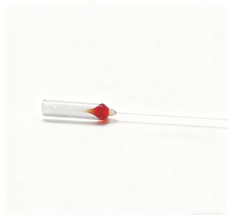
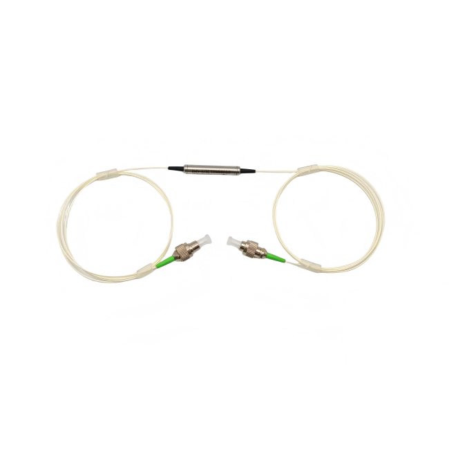
An L band polarization insensitive optical isolator supplier should be given the amplifier or transmission band before the buyer discusses connector style. Feiyi’s L-Band Polarization-Insensitive Optical Isolator is listed in single- and dual-stage forms for L-band systems, using Corning SMF-28 fiber and a compact 5.5 mm cylindrical package. The single-stage table covers 1570–1600 nm, while the dual-stage table covers 1565–1610 nm. Those ranges are the first filter for an EDFA, Raman amplifier, DWDM line or fiber-laser architecture.
This product is not the same purchasing decision as a polarization-maintaining isolator. The L-band device is designed for a signal whose polarization state should not have to be aligned to a PM slow or fast axis. A buyer working with standard single-mode transmission fiber should therefore focus on wavelength coverage, isolation, insertion loss, PDL, PMD, return loss, power and package rather than introducing a PM-axis requirement that the product does not use.
An L band polarization insensitive optical isolator supplier should start with the real L-band channel plan
“L-band” can describe a broad region, but the Feiyi tables provide more specific operating windows. The single-stage product is listed at 1570–1600 nm with a ±15 nm bandwidth line, while the dual-stage table extends from 1565 to 1610 nm. The buyer should compare the actual WDM channel plan, amplifier gain window or source tuning range with the selected stage instead of assuming that every L-band wavelength is covered equally by every configuration.
For a DWDM project, write the lowest and highest used channels into the request. For an amplifier module, include the intended gain band. If a future network expansion is expected to add channels near an edge of the current range, make that visible during qualification rather than discovering the limitation after the first production run.
Coherent’s single-side isolator documentation is a useful external example of how telecom isolators are specified by wavelength window, insertion loss, isolation, PDL and PMD as separate parameters. Its values are not Feiyi specifications; the comparison is useful because it shows why a wavelength label alone cannot qualify an installed L-band isolator.
Single-stage coverage should be checked against the channels actually present
Feiyi’s single-stage table lists 1570–1600 nm. A system using only a subset of that interval should still record the exact channel range at acceptance. If the network later adds a wavelength outside the approved set, the isolator should be rechecked rather than assumed to cover the expanded plan because the equipment is still generally described as L-band.
A distributor selling into mixed telecom projects should keep the operating window in the item description. “L-band isolator” is too broad to distinguish the listed single-stage and dual-stage wavelength coverage.
Single-stage and dual-stage Feiyi isolators trade forward loss for stronger reverse suppression
The Feiyi single-stage P-grade table lists typical isolation of at least 41 dB and minimum isolation of at least 30 dB. The A-grade column lists typical isolation of at least 40 dB and minimum isolation of at least 28 dB. For the dual-stage form, the P-grade values rise to at least 50 dB typical and 45 dB minimum, while the A-grade values are at least 45 dB typical and 40 dB minimum.
The buyer should not choose dual stage simply because the isolation number is higher. Dual-stage isolation can be valuable when an amplifier or transmitter needs stronger protection from backward light, but the added optical path also changes insertion loss. Feiyi lists typical single-stage insertion loss of 0.4 dB for P grade and 0.5 dB for A grade, with maximum values of 0.6 and 0.8 dB. The dual-stage table lists 0.65 and 0.80 dB typical, with maximum values of 0.80 and 1.2 dB.
An EDFA designer should assign isolation and insertion loss to different parts of the budget
In an L-band EDFA, reverse suppression protects the amplifier or upstream source from unwanted backward propagation, while insertion loss consumes forward signal margin. Put both requirements in the module budget. A configuration that delivers more isolation than necessary but pushes the forward loss beyond the system target is not automatically the better purchase.
A service replacement should preserve the same stage and grade unless engineering has reviewed the tradeoff. The cylindrical package can look similar across versions, so optical identity must come from the controlled item description rather than appearance.
PDL and PMD matter because the L-band signal polarization is not fixed
A polarization-insensitive isolator is useful precisely because the incoming state can vary. Feiyi lists PDL at no more than 0.05 dB for P grade and 0.1 dB for A grade in both stage tables. That metric should remain separate from ordinary insertion loss: PDL describes how loss changes with polarization state, while insertion loss describes the forward attenuation under the specified measurement.
The single-stage table lists PMD of 0.25 ps, with 0.05 ps available upon request. The dual-stage table lists 0.05 ps. A high-capacity DWDM system or precision transmission test may care about the lower PMD option even when the average power budget is generous. If PMD is part of the network design, put the required limit into the order instead of leaving it as an optional catalog line.
For an L-band amplifier module
Confirm the amplifier gain window, required reverse isolation, allowed forward loss, PDL, power and the selected single- or dual-stage grade.
For a DWDM transmission link
Map the used channels against the stage’s operating window and specify PMD if dispersion sensitivity makes it part of the link budget.
For distributor inventory
Keep stage, grade and wavelength window in the stock identity. Do not replace one L-band variant with another based only on the same package diameter.
Return loss should be tied to the selected grade at both ends of the isolator
Feiyi’s P-grade return-loss line is at least 65/60 dB for input/output, while A grade is at least 55/55 dB. These values help a buyer define how the isolator interfaces with other fiber components in a reflection-sensitive chain. Keep the input and output values associated with the correct grade rather than quoting the strongest number as a general family claim.
Connector selection can affect the complete installed reflection behavior. The product page identifies the optical component and fiber package; if the order adds a particular connector or splice arrangement, the buyer should define the test reference plane and the interface that will be present in production. A component-level return-loss figure does not automatically describe every mated connection in the final network.
The SMF-28 pigtail makes this a different interface from Feiyi’s PM isolator families
Feiyi lists Corning SMF-28 for the L-band polarization-insensitive device. That is consistent with a telecom component designed to accept varying input polarization. It should not be replaced casually with a PM pigtail merely because the project also contains polarization-maintaining components elsewhere. Changing the fiber type changes the interface and the reason the device was selected.
For a network integrator, this distinction is useful when the same chassis contains both standard telecom channels and a specialized PM sensing branch. Keep the L-band isolator on the standard single-mode route unless the optical architecture has been deliberately redesigned. Feiyi’s PM isolator family belongs to a different polarization-control problem.

The 300 mW power line and 5.5 mm package should be checked where the isolator sits in the amplifier
Feiyi lists 300 mW power handling for both stage tables and a 5.5 mm × 35 mm package. Operating temperature is listed from -10 to +75 °C and storage from -40 to +85 °C. Those values should be compared with the power and thermal condition at the actual installation point, not with the total system output if the isolator sits somewhere else in the chain.
An L-band amplifier designer may place an isolator before or after a gain stage depending on the architecture. The optical power reaching the component can therefore differ substantially even within the same module. Show its location on the block diagram and qualify that location. If the final design can exceed the listed power condition, request a specifically confirmed alternative instead of carrying the 300 mW part into the new location.
A small cylindrical body still needs fiber-exit and service-loop clearance
The 5.5 mm × 35 mm body is compact, but the installed envelope also includes pigtails and any connectorized service loop. A dense amplifier tray can leave enough space for the cylinder while bending the fiber too sharply at the exit. Mechanical approval should include the actual routing path, not only the body dimensions.
OADM, DWDM and amplifier components around the isolator should remain separate procurement functions
Feiyi’s DWDM Module separates or combines wavelength channels; the DWDM OADM Module adds or drops selected channels; an EDFA rack-mount unit provides optical gain. The L-band isolator performs one-way optical protection. These products can appear in the same transport architecture but should not be compared as alternatives simply because all work in fiber networks.
A useful procurement diagram names the optical job beside each block: gain, wavelength multiplexing, add/drop, or reverse-light suppression. That makes it easier for purchasing and a supplier to recognize when an item has been substituted with the wrong function.
Network expansion from C-band toward L-band should trigger a new isolator check
A carrier or equipment maker may add L-band channels to increase capacity while retaining parts of an existing C-band platform. The fiber plant can remain the same while the passive component requirements change. An isolator qualified around a C-band amplifier should not be assumed to cover the new L-band channels. Compare the new wavelength plan directly with Feiyi’s listed 1570–1600 nm single-stage or 1565–1610 nm dual-stage range.
The reverse situation also matters during repairs. A service team may find an L-band isolator physically compatible with a nearby C-band unit. Package compatibility does not establish optical compatibility. Keep wavelength range in the replacement label so a maintenance decision cannot be made from body size and connector type alone.
Receiving records should retain the P-grade or A-grade identity
Because Feiyi publishes separate P- and A-grade columns, the delivered grade should appear on the purchase and inspection record. Isolation, insertion loss, return loss and PDL limits differ by grade. If the first approved batch is P grade, a later A-grade substitution should be evaluated as a specification change rather than accepted because both devices share the same wavelength family.
Repeat orders should preserve the stage, grade and channel window that the network actually qualified
After an L-band isolator passes system testing, keep the selected single- or dual-stage configuration, P/A grade, operating window, PDL/PMD requirement, return-loss limits, SMF-28 interface, 300 mW class and package in the controlled item record. A future order that says only “L-band polarization-insensitive isolator” leaves too much room for an unintended variant.
Feiyi’s fiber optic isolator manufacturer article discusses changing polarization states in a broader context, while the site’s WDM/CWDM/DWDM overview can help place L-band components inside a wavelength-division network. The final approval for this isolator should still use the exact Feiyi L-band stage and grade that matches the channel plan.
For a real purchase, the shortest useful technical handoff is specific: wavelength range, stage, grade, isolation target, loss budget, PDL/PMD requirement, return-loss condition, power at the isolator location, fiber interface and package. Once those are visible, the supplier can offer an L-band build that the buyer can verify without relying on a generic “telecom isolator” description.