PM 630nm Fiber Patch Cord Manufacturer: Lock Axis and Polish Before Cable Assembly
PM 630nm Fiber Patch Cord Manufacturer: Lock Axis and Polish Before Cable Assembly
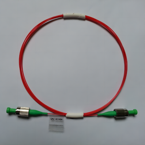
A PM 630nm fiber patch cord manufacturer order should define the polarization axis and connector polish before cable color or boot style. Feiyi’s PM 630nm Optical Patch Cord is listed for 630 nm operation with PM780 fiber, insertion loss no greater than 0.2 dB in the displayed connector table, a minimum extinction ratio of at least 22 dB, multiple FC/SC/LC/ST/MU/MTRJ connector families, and customizable axis direction. For short-wavelength sensing, test equipment or optical transmission, those optical interfaces matter more than cosmetic assembly choices.
The buyer should first state whether the fast axis, slow axis or a custom orientation is required and how that orientation is referenced at each end. Then select UPC/APC where available and the connector family that matches the installed equipment. A 630 nm patch cord is not simply a standard fiber jumper with a different wavelength label; the PM-axis relationship is part of the delivered component.
A PM 630nm fiber patch cord manufacturer needs the axis convention before connector assembly
Feiyi lists fast-axis, slow-axis or customized axial direction. That option should be written into the drawing at both ends of the cable. If a connector key is used as the mechanical reference, define how the PM axis relates to the key. If one end uses a different connector family, do not assume that the same physical keying convention is obvious to the assembler.
External PM cable documentation reinforces this practice. Thorlabs’ PM patch-cable documentation explicitly treats connector-key-to-axis alignment as a controlled cable property. Its tolerances are not Feiyi specifications, but the engineering principle is directly relevant: a PM patch cord should carry an axis definition through the connector interface.
A visible-light or short-wavelength bench should label the axis at both mating points
On a research bench, cables are frequently disconnected and reconnected. If the axis reference exists only in an engineer’s notebook, a cable can be rotated or replaced incorrectly during service. Add axis identification to the controlled cable record and, where practical, to the equipment interface drawing.
For an OEM build, preserve the same convention in work instructions so a production assembler does not treat the PM patch cord as a normal jumper.
630 nm operation should be matched to the actual source rather than inferred from the cable jacket
The Feiyi page identifies 630 nm as the operating wavelength. A buyer working with a source near that region should state the actual nominal wavelength and any meaningful tuning or drift. If the project later moves to 780 nm or another source family, use the corresponding Feiyi PM patch-cord product instead of assuming the 630 nm cable remains appropriate.
The page lists PM780 as the fiber specification even though the patch cord is labeled 630 nm. Because this is a specific manufacturer configuration, the buyer should preserve that listed fiber choice in the first quotation and ask for confirmation if a different fiber is needed. Do not silently replace it with another PM fiber based on the wavelength name alone.
Fiber identity belongs in repeat orders because it affects the optical interface
A replacement cable with the same connector and length can still be a different optical assembly if the PM fiber changes. Keep the approved fiber type in the item description, especially when a system uses several PM cable wavelengths in the same rack or lab.
UPC and APC choices should follow the reflection sensitivity of the 630 nm instrument
The Feiyi connector table includes UPC and APC variants for some connector families and lists different return-loss values by connector/polish combination. For example, the table displays return-loss values up to at least 60 dB for one APC column and lower values for some other connector types. The buyer should attach the return-loss requirement to the actual connector pair being used rather than quoting the highest number from the table as a universal cable specification.
A sensor or interferometric bench that is sensitive to back reflection may prefer an angled polish where the mating equipment supports it. A general test lead may use another connector for compatibility. The correct decision is the one that matches both ends of the real instrument.
Do not mate APC and UPC interfaces as if the polish were only a naming difference
Connector family and polish must match the equipment port. A cable can have excellent PM alignment and still create an unusable interface if the mating polish is wrong. Put both connector type and polish into the part description, not just “FC” or “SC.”
Insertion loss and extinction ratio should be tested under the approved axis alignment
Feiyi lists insertion loss at no more than 0.2 dB across the displayed connector table and a minimum extinction ratio of at least 22 dB. These numbers answer different questions. Insertion loss describes how much wanted power is lost through the cable; extinction ratio describes polarization preservation. A low-loss cable can still be poorly aligned to the required polarization axis.
For incoming inspection, launch the cable under the same axis convention used by the instrument. If the test setup ignores orientation, the measured extinction-ratio result will not represent the installed condition. Record the cable-end identities so the same direction can be reproduced on a later batch.
Two 630 nm purchase scenarios need different cable priorities
Precision sensor or interferometer: prioritize axis definition, connector polish, return loss and extinction ratio. General test lead: prioritize compatibility, repeated mating durability and a clearly labeled axis so the cable can be reconnected without losing the polarization reference.
Mechanical endurance matters when a 630 nm PM cable is used as a service lead
Feiyi lists repeatability at no more than 0.1 dB, interchangeability at no more than 0.2 dB, at least 1000 plug cycles, tensile strength of at least 100 N and durability change no more than 0.2 dB. These values are relevant when the patch cord is repeatedly connected to test equipment rather than permanently installed.
A laboratory cable that is moved daily should be inspected for connector cleanliness, boot strain and fiber routing before an optical drift is blamed on the PM fiber itself. A production cable inside a fixed enclosure may care more about bend management and strain relief than mating cycles.
The operating-temperature row on the current 630 nm page should be confirmed before it becomes a procurement limit
The current Feiyi 630 nm table appears to contain an anomalous operating-temperature entry that does not read like a valid temperature range. It should not be converted into a firm purchasing specification by guessing what was intended. The page does list storage from -45 to +85 °C. If the project has an environmental requirement, request the current confirmed operating-temperature range for the exact 630 nm cable build.
This is a useful quality-control step rather than a reason to discard the product page. The page reliably establishes the product family, connector options, optical values, fiber listing and mechanical endurance; the questionable temperature row simply needs a current manufacturer confirmation before it is written into a controlled drawing.
Connector variety should be used to match installed equipment, not to create unnecessary cable variants
Feiyi lists FC, SC, LC, ST, MU and MTRJ families and customizable boot colors. A distributor can easily create too many nearly identical stock items if every connector and color combination is treated as a general-purpose cable. Stock the interfaces that match real customer equipment and keep wavelength, PM axis and polish in the SKU.
Boot color can help visual management, but it should not become the only indicator of optical identity. The product page notes common housing colors such as blue, green, beige and aqua for broader fiber conventions; a PM 630 nm cable should still carry an explicit product label so users do not identify it by color alone.
A mixed-connector PM cable needs an end-by-end drawing
If one end is FC/APC and the other is LC/UPC or another combination, label each end separately. The drawing should show which instrument port receives each connector and how the axis reference is preserved across the cable. This prevents a replacement cable from being built with correct parts in the wrong orientation.
A 630 nm patch cord used in test equipment should have a cleaning and reconnection reference
Short-wavelength systems can be sensitive to contamination at small optical interfaces, and a cable that is repeatedly connected in a lab can accumulate a condition that changes loss or reflection. The procurement file does not need to invent a maintenance program, but the user should know which connector end was cleaned and measured when the cable was accepted. That makes later troubleshooting more useful than comparing a field cable with an undocumented new-cable reading.
If an engineer sees insertion loss increase after many reconnections, inspect the connector faces and mating adapters before concluding that the PM fiber has changed. The listed plug-cycle and repeatability figures describe the product’s intended mechanical use, but actual connector cleanliness remains part of the installed interface.
A replacement cable should be checked in the same direction if the end connectors differ
When both ends use the same connector, cable direction may be mechanically less obvious. With a mixed-connector build, however, the installed direction is fixed by the equipment. Record which end was used as the launch end during acceptance so the next cable can be compared under the same physical condition.
This also helps when return loss differs by connector polish. A result measured from one end of a mixed UPC/APC assembly should not be compared casually with a result measured from the opposite end.
Length should be chosen from the installed route, not from an arbitrary catalog default
A long PM cable can add routing slack, bend-management difficulty and more opportunities for mechanical disturbance. A cable that is too short can pull on ferrules and adapters. Specify the finished length from the actual instrument route and service access requirement. If the build moves from a lab table to an enclosure, remeasure the path instead of carrying the prototype length forward automatically.
For distributor stock, a small set of common lengths can be useful, but a customer-specific axis and connector arrangement should remain distinct even when the length is standard. A cable should not be substituted purely because another item reaches the same two physical ports.
PM 630 nm patch cords belong in a broader PM connectivity family, not a universal jumper pool
Feiyi also lists PM 780nm, PM 850nm, PM 980nm, PM 1064nm, PM 1310nm and PM 1550nm versions. These wavelengths should be treated as distinct optical items even when the connectors and cable jackets appear similar.
For a lab or distributor storing several variants, make wavelength and fiber type visible on the label. That reduces the chance that a mechanically compatible cable is installed into the wrong optical source chain.
Repeat orders should preserve the approved 630 nm axis, polish and fiber identity together
Once a cable passes the instrument test, retain the 630 nm wavelength, PM780 fiber listing, axis orientation, end-by-end connector types, polish, cable length, boot/strain-relief configuration and the optical acceptance values used for that build. A repeat order described only as “630 nm PM patch cord” is not enough to reproduce a polarization-sensitive interface.
Feiyi’s PM patch-cord axis-alignment article gives broader supplier context, while the exact 630 nm product page should remain the source for current Feiyi options. Before release, make sure the cable drawing can be understood by someone who never saw the original optical bench.