Coaxial Fiber Collimator Supplier: Define the Short Working Distance and Optical Axis
A compact optical head can lose alignment before it loses transmission. For an OEM placing a fiber interface inside a sensor, amplifier or laser assembly, a coaxial fiber collimator supplier should therefore receive the optical-axis drawing before the housing diameter is approved. Feiyi’s coaxial collimator is a starting point for short working distances; its listed 5–10 mm range should not be mistaken for the 200 mm arrangement offered by the separate single-mode and multimode products. Confirm wavelength, fiber and the receiving geometry first.
The practical question is whether the purchased assembly can deliver useful light through the available aperture while leaving room to mount, terminate and protect its fiber. A small cylindrical package does not answer that question on its own. The supplier needs the location of the receiving surface, the direction of the optical axis and the conditions under which the delivered assembly will be measured.
A coaxial fiber collimator order starts at the receiving aperture
The coaxial collimator is most useful to evaluate when the fiber and downstream optics must fit into a tightly constrained mechanical path. Feiyi lists fiber lasers, optical amplifiers, LiDAR, communications and sensing among its applications. Those labels identify possible uses, but the aperture and optical geometry decide whether this particular short-distance part belongs in the design.
Define the 5–10 mm working distance from an agreed lens datum
A distance on a drawing is only useful when both parties measure from the same reference. State whether the receiving surface is located from the lens exit, the housing end or another mechanical feature. Add a dimensioned sketch showing the clear aperture and any window between the collimator and receiver. Otherwise, two assemblies can share the same stated distance while placing their light at different physical locations.
For a sensing-head designer, the available axial space may already be fixed by a window carrier. The correct discussion is then about the beam at that carrier and the receiving optic beyond it. Moving the lens to make the mechanical envelope fit can change the optical arrangement. Treat that change as a new sample condition, rather than assuming a 5 mm and a 10 mm installation are automatically equivalent.
The 0.1° pointing entry needs the same housing reference as the mount
Pointing accuracy describes a direction; the mounting bore establishes another direction. The drawing should show the relation between them. A buyer using a cylindrical sleeve should identify the engagement length, allowed rotation and method of securing the body. Ask for the pointing reference used for the supplied assembly, especially if the fixture contacts only a short section of the housing.
Do not turn the published pointing entry into a guaranteed coupling result. A receiver displaced sideways, a tilted window or a restricted aperture can reduce collected power even when the collimator itself meets its directional requirement. The mechanical review should therefore include the downstream hardware, not only a pass or fail measurement of the loose component.

Which fiber belongs in the coaxial collimator assembly?
Feiyi’s table distinguishes 850 nm from the 1310/1550 nm options and lists both single-mode and multimode fiber. Its ordering information also names G657A1, 50/125 and 62.5/125 choices. The presence of several fiber choices does not mean that an assembly qualified with one of them reproduces the same beam when another is substituted.
850 nm multimode fiber needs a launch description
When the input is multimode, describe the source and the fiber core used in the system. A device receiving light from a 50/125 fiber should not be approved using an undocumented 62.5/125 laboratory lead merely because both are called multimode. Record how the source is coupled and whether the test includes the same intermediate connectors as the equipment.
A distributor supplying optical heads to different instrument builders may need separate configurations rather than one generic coaxial item. A mechanical dimension can be common to those configurations while the launch fiber and receiving optics differ. Keeping separate order descriptions prevents an apparently identical spare from entering the wrong assembly line.
1310 and 1550 nm single-mode interfaces need a wavelength-specific sample
The coaxial listing gives typical insertion loss of no more than 0.8 dB and maximum insertion loss of no more than 1.0 dB, with return-loss entries that differ by wavelength grouping. Use the selected wavelength and fiber combination when discussing these values. Do not combine the best numbers from different columns into a specification for an untested configuration.
Feiyi states that the table is measured at 25°C without connectors. A connectorized instrument therefore requires an additional reference definition: what is included between the input and output measurement planes? If a test lead is added during receiving inspection, distinguish that connection from the intrinsic assembly rather than rejecting a part against a connectorless figure.
For general optical context, Thorlabs’ collimator explanation relates beam behavior to wavelength and the input fiber. It helps explain why these conditions belong in the engineering request; its own lens designs and performance figures are not specifications for Feiyi products.
The coaxial ordering information offers C-lens and G-lens descriptions. Preserve the selected lens construction in the approved drawing instead of accepting an unspecified change because the replacement housing fits. The buyer’s concern is the optical result at the short receiving distance, not the lens name alone. If an alternative construction is proposed, compare it under that same input and receiving condition before changing the order.
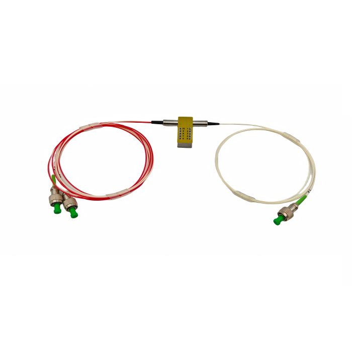
Pigtail lengths of 0.5, 1 and 1.5 m appear in the ordering information. Choose the usable length from the actual route inside the head and to its service connection. Extra fiber can create an unnecessary loop near the lens holder, while a short lead can pull on the exit during assembly. Define the length datum and termination with the sample; neither should be left to the receiving technician to reconstruct.
Short coaxial packaging and 200 mm collimation solve different problems
A compact housing should be compared with other products according to the optical job it must perform. The useful alternatives in Feiyi’s range include a long-distance single-mode assembly, a long-distance multimode assembly and a general single-fiber collimator. They provide distinct starting points, rather than a progression in which the longest distance is necessarily better.
| Feiyi option | Decision it helps resolve | Reason to keep the comparison separate |
|---|---|---|
| Coaxial collimator | A short optical path inside a compact head | Its listed 5–10 mm range is not the 200 mm specification |
| Single-mode collimator, WD 200 mm | A longer free-space interface with G657A1 fiber | Wavelength, receiving optics and mounting length change |
| Multimode collimator, WD 200 mm | A 50/125 multimode path at 850 or 1310 nm | The launch and collection conditions need their own approval |
| Single-fiber collimator | A broader lens, fiber and termination configuration | The selected working distance still requires definition |
The single-mode WD 200 mm collimator lists 1310/1550 nm, G657A1 fiber and a 2.4 × 14 mm body. Consider it when the optical arrangement truly requires a longer receiving distance. It is not a direct replacement for the coaxial body merely because the wavelengths overlap.
The multimode WD 200 mm collimator lists 850/1310 nm and 50/125 fiber, with its own loss and return-loss figures. This option belongs in a multimode design review, rather than being treated as the less expensive version of a single-mode assembly. The receiving optic may collect a different spatial distribution of light.
Feiyi’s single-fiber collimator gives another route when a buyer needs to discuss lens, fiber and termination choices together. Use it to establish a configuration, then compare the approved configuration with the coaxial arrangement. A family name alone cannot confirm the dimensions of the replacement.
Give the coaxial fiber collimator supplier two acceptance views
Approval should distinguish the loose optical component from the component installed in its mount. The first view checks the supplied wavelength, fiber, termination and optical behavior. The second checks what changes after the housing is seated and its pigtail is routed inside the equipment. Both views are needed when the mechanical envelope is the reason for choosing this product.
Begin the component check with clean, matching connections and a recorded source setting. Measure the agreed transmission quantity at the selected wavelength, then inspect where the beam falls at the receiving plane. If the component is supplied without connectors, define the temporary interface used for this measurement and preserve it during comparison of samples.
Next install the same component in the intended holder. Compare the collected power and beam position before and after securing it. This is a proposed approval method, not a claim that Feiyi has performed a particular test for your assembly. Its purpose is to reveal whether the mount, adhesive process or fiber exit is changing the optical result that justified purchasing the part.
The listing gives a 0.5 W power-handling entry. Establish whether the actual source is continuous or pulsed and what enters the supplied component; do not infer a pulsed peak-power rating from the table. Likewise, an operating-temperature range is not evidence that an installed housing has passed the buyer’s particular thermal cycle or vibration requirement.
Protect the coaxial lens face without loading the pigtail
For this small body, receiving and storage instructions should prevent lens contamination and fiber-exit strain. Ask that the agreed protective arrangement keep the optical face away from loose packaging material and identify how the fiber will be restrained during transport. These are requirements to agree for the order, rather than a description of an undocumented standard packing method.
A production buyer should also separate the optical assembly from accessories in the purchase record. If a sleeve, connector or protective cap belongs to the approved sample, identify whether it is supplied with the repeat order. The small body dimensions make an omitted mounting accessory consequential: the receiving team may otherwise improvise a holder and unknowingly change the axis reference.
For a polarization-sensitive instrument, the PM collimator interface guide addresses the additional axis questions. An ordinary coaxial request should not silently acquire a polarization-maintaining guarantee. Resolve that requirement before deciding which product family can meet the equipment’s optical behavior.
Send the supplier the short-distance drawing, the selected input fiber and the receiving-plane measurement together. Approve a coaxial assembly only when those three descriptions agree with the mounted sample. If the useful light must travel 200 mm, or a polarization axis must be preserved, move that requirement into the appropriate collimator configuration before treating the compact body as a finished purchase decision.