
Approving a 10G DWDM SFP+ Transceiver Supplier for the Installed ITU Channel
“ITU channel 35” is a useful starting label, but an installed DWDM circuit needs a more complete module identity. Engineers approving a 10G DWDM SFP+ transceiver supplier should match the exact channel assignment, passive-filter spacing and receiving limits before treating a spare as interchangeable. Feiyi’s 10G DWDM SFP+ transceiver lists ITU-grid channels 17–61 and 40 km/80 km ordering rows. It is relevant to 10G equipment buyers evaluating DWDM links; the first approval should identify the configured module and the route it must preserve.
A replacement at one endpoint should maintain the original service’s channel, host format and optical relationship with the far-end receiver. A new service through an existing DWDM assembly needs confirmation that the proposed frequency actually belongs to the available port. These tasks use the same product family but require different evidence. A broad channel range in a catalog does not establish that a particular unit covers every channel or that its frequency is tunable.
Identify the installed DWDM channel by its approved frequency
The Feiyi SFP+ family describes an ITU-grid range of 17–61. Obtain the center frequency or wavelength and the supplier’s channel designation for the selected version. Retain them together on the order and technical document. This avoids a mismatch when an installer, equipment label and supplier worksheet use different shorthand for the same channel.
Channel numbering is not a substitute for DWDM spacing
The 3-port DWDM device includes 100 GHz and 200 GHz options. The transceiver’s wavelength assignment must be evaluated with the selected filter’s actual passband. Choosing a module from the listed channel range does not, on its own, approve every filter spacing or every passband implementation.
For engineering context, ITU-T G.694.1 defines the DWDM frequency grid. Use the grid to make the channel designation unambiguous. It does not certify the optical tolerances or compatibility of a particular transceiver-and-filter combination.
Consider a maintenance engineer replacing a failed optic on an otherwise unchanged circuit. The old module label may show a channel number, while the mux drawing gives a wavelength. Reconcile those identifiers before selecting a spare. If the old unit is unavailable, recover the channel from the approved circuit record and passive assembly rather than inferring it from a neighboring port.
A DWDM module port must be tied to the circuit drawing
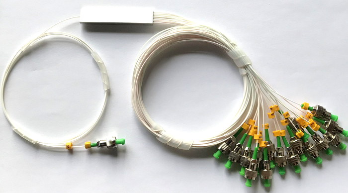
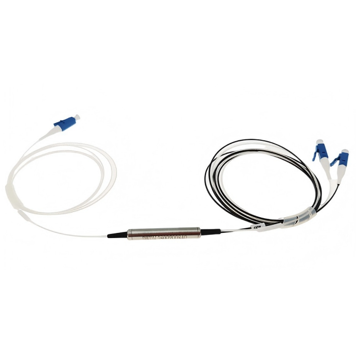
Feiyi’s DWDM module represents the assembled passive channel route. The buyer needs its configured port map, including the common connection and the channel intended for each endpoint. A label such as “DWDM module” does not tell receiving staff how the ordered SFP+ should be connected.
An OEM purchasing optics and passive assemblies from the same range can use one channel schedule for both. Have each line identify the port, configured center and optical direction. This makes an error visible at the document stage, before two valid but mismatched products are connected in a rack.
Read the 10G DWDM SFP+ ordering rows without inventing optical limits
The published table lists XKSFC-XX96-80BD as a 10G, 80 km row with DWDM ITU-grid 17–61, DFB/PIN and LC/PC entries. XKSFC-XX96-40BD is listed at 10G and 40 km with the same channel range, EML/APD and LC/PC. Both rows include a DDM Y/N field. These are family selection records, not a complete specification for each configured module.
The ordering prefix resembles the prefix used on another Feiyi transceiver family. Preserve the DWDM product identity and the exact configured wavelength on the approved order. A part-number fragment alone should not decide whether an optic is CWDM or DWDM, especially when an internal purchasing database stores only abbreviated descriptions.
| Information present in the family table | Information still needed for approval |
|---|---|
| 40 km or 80 km row | Transmitted-power range, receiver sensitivity and overload |
| ITU channels 17–61 | Configured center and supported optical tolerance |
| LC/PC interface | Approved mating cord, polish and connector contribution |
| DDM Y/N | Whether diagnostics are included in this ordered version |
A buyer should not replace the listed transmitter-and-receiver combinations with assumptions from another manufacturer’s catalog. Obtain the configured specification if the row appears unusual or incomplete. The acceptance document needs to be internally consistent with the product supplied, not merely similar to a familiar optic.
Receiver overload matters when the replacement link is shorter
For a long path, the sensitivity limit helps establish the minimum received power. For a short path, the overload limit helps establish the maximum. A replacement carrying an 80 km label may have optical limits different from the unit it replaces. A shorter distance does not automatically make the substitution safe or suitable.
Use the actual two-end optical limits and route loss to decide whether additional attenuation is required. Keep the approved attenuation arrangement with the circuit record. Prescribing a standard attenuation value from the distance label alone can create a new problem by reducing the receiving margin on an already lossy filtered path.
Keep filter behavior and transmitter stability in the same DWDM review
A transceiver and a filter can have acceptable individual specifications while their combination needs further review. Obtain the selected module’s optical center and relevant tolerance, then compare them with the approved filter passband and the equipment’s operating conditions. Do not use a nominal center match as a complete temperature or operating-range approval.
The 3-port DWDM product distinguishes transmission and reflection loss and gives different passband entries for 100 GHz and 200 GHz versions. Identify the path taken by the selected channel. If several individual filters are cascaded, account for the actual sequence rather than assigning a single generic loss number to the entire DWDM arrangement.
A circuit expansion can change that sequence. The existing channel may remain on its original center frequency but pass through an added passive element. Review its optical margin after the expansion as well as the new channel’s margin. A successful new circuit does not prove that the existing circuits retain their approved reserve.
For a sample test, document the passive assembly configuration along with the module. A low received-power reading could arise from the wrong filter port, an external connection or the optical characteristics of the module. Changing several elements together prevents the test from locating the source of the change.
For a replacement circuit with different wavelengths in its two directions, list each transmitter and the corresponding far-end receiving path separately. A passive map may place the outgoing and incoming light on different filter routes. The channel of the local transmitter therefore cannot identify every optical connection involved in the service. Keep both directions visible when checking the spare and the patching instructions.
Do not describe the catalog’s 17–61 range as a tuning range for one module. The page establishes a family selection range but does not supply a tuning-control interface or an approved tunable configuration. If the equipment requires a frequency-agile optic, obtain explicit confirmation of that behavior. For a fixed configured optic, its delivered channel should be identifiable before connection.
The same distinction affects distributor stocking. Several approved fixed-channel units can cover several circuit assignments, while one unidentified unit cannot be assumed to replace all of them. Organize stock against the actual service configurations and retain the supplier’s configured-channel identity. A receiving operator should not rely on host insertion as the first method of discovering a module’s wavelength.
When a sample is tested over a temporary laboratory route, record how that route differs from the deployed DWDM assembly. Successful operation without the production filters demonstrates a narrower result than successful operation through them. Preserve that boundary in the approval record so that the laboratory result is not later treated as full circuit qualification.
A 10G DWDM SFP+ transceiver supplier should distinguish host approval from optical approval
Feiyi describes hot plugging, an SFP+ footprint, built-in diagnostics and power dissipation below 1.5 W. The commercial case-temperature range is 0 to +70°C, with an industrial −40 to +85°C option. Those entries help screen a design; they do not supply a named host compatibility record for every switch, router or transport platform.
Specify the exact host port and intended service when arranging a sample. Check that the module is recognized, that the intended application operates and that the required diagnostics can be read. The optical path through a mux is a separate part of that review. A host-recognized optic on the wrong channel can still fail to deliver the intended service.
DWDM XFP and lower-rate SFP variants preserve different interfaces
The 10G DWDM XFP transceiver belongs to equipment using the XFP format. The line-side wavelength may be relevant to the same network, but the module is not a mechanical replacement for SFP+. Verify the installed format before exchanging an optical selection between the two product families.
Feiyi’s 1.25G/2.5G DWDM SFP transceiver serves a lower-rate equipment requirement. A distributor stocking several generations of DWDM equipment should separate rate and format in the inventory description. Similar metal housings and a shared channel name are insufficient identifiers for a service spare.
For a mixed-temperature stock order, preserve the approved commercial or industrial version with each module’s channel. The installed module case can experience different conditions from the rack’s room ambient. If a higher-temperature version is proposed as a substitute, confirm the optical and host approval for that version rather than assuming the temperature entry is the only difference.
Use receiving evidence to preserve the configured DWDM service
The receiving record should show the supplied channel, module family, temperature version and diagnostic option. Reconcile it with the order before inserting the module into a live system. Optical-interface protection and labeling should keep those identities intact through unpacking, storage and installation. A shared family photograph cannot identify the configured center of an individual unit.
For a maintenance purchase, agree whether the supplied document identifies a direct replacement or a new configuration that still needs qualification. Keep the optical acceptance conditions with the part description. If a purchasing substitution changes the receiver type, wavelength tolerance or temperature version, return it to the engineering review before installation.
Feiyi’s 40-channel DWDM assembly discussion offers context for the passive network. This module purchase should retain the specific channel and endpoint requirements inside that larger arrangement, including the route used when commissioning the replacement.
Request the delivery schedule and packing arrangements for the actual channel mix. A product family listing a channel range is evidence of its published selection scope, not proof that every wavelength and temperature version is in inventory. Plan installation around the confirmed order, rather than around an assumed uniform lead time.
Approve the spare when its configured center, host operation and receiver limits preserve the intended DWDM circuit. If only a channel number and distance label are available, the review is incomplete. Recover the frequency record and two-end optical limits before making a substitution that appears convenient in the purchasing system but remains uncertain in the fiber path.