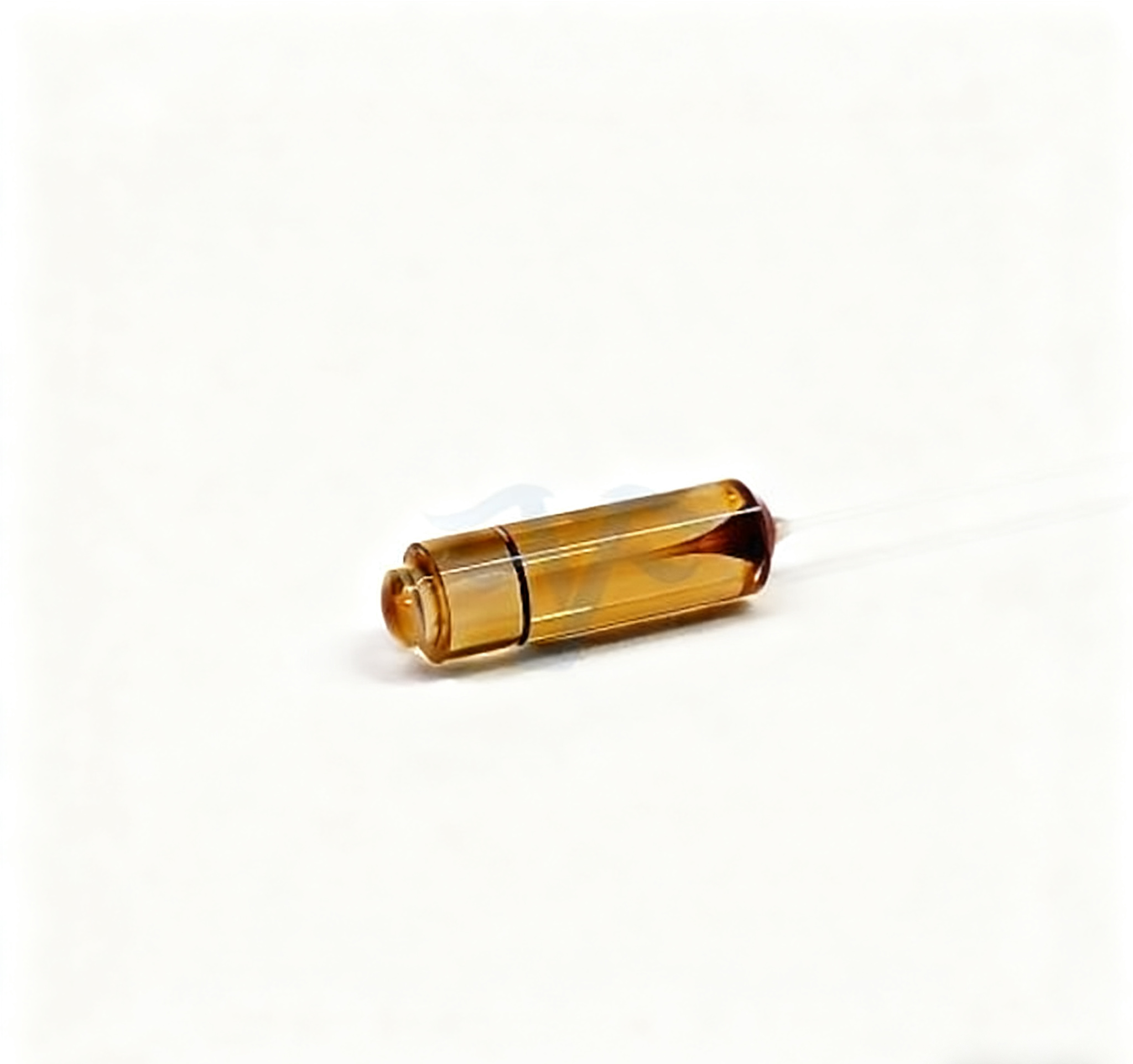
When a PM Fiber Collimator Manufacturer Needs More Than Your Working Distance
A free-space gap can look straightforward on an optical diagram: light leaves a PM fiber, crosses an element and enters another PM fiber. In the assembly, beam size, pointing, polarization and the receiving interface must all agree. A buyer working with a PM fiber collimator manufacturer should define those interfaces before approving a working-distance number. Feiyi’s PM 1550 nm collimator is a relevant starting point for telecom-band assemblies, while its custom PM collimator range provides lens, housing and working-distance choices that require a project-specific drawing.
Give the PM fiber collimator manufacturer the beam requirement at a named plane
“A small beam” is not a sufficient acceptance condition. Identify where the beam will be measured, how its diameter is defined and what aperture or optical element it must pass through. Feiyi’s PM 1550 nm collimator lists a beam diameter below 0.5 mm, but the buyer still needs the applicable measurement convention and location for the selected build. Do not use that entry as a promise of unchanged diameter at every point in the instrument.
The 1550 nm PM collimator’s beam must fit the free-space element
Consider an instrument that passes a 1550 nm beam through a polarization-sensitive element before coupling it back into fiber. The outgoing beam must fit the element’s usable aperture, and the receiving optics must accept the transmitted beam. Set the beam requirement at the element and at the receiving interface rather than measuring only next to the emitting housing. Those locations can reveal different alignment and propagation issues.
Thorlabs’ pigtailed-collimator technical discussion explains that beam diameter and divergence depend on wavelength, fiber and lens. A collimated beam can still expand over propagation distance. For the Feiyi assembly, request the beam condition that fits the actual gap instead of deriving an unlisted divergence value from a photograph.
The PM 1550 nm listing gives P-grade and A-grade maximum insertion-loss entries of 0.21 and 0.25 dB, and return-loss entries of 65 and 62 dB. Preserve the selected grade in the order. These component entries should not be used to predict the total loss of a free-space path containing an additional element, receiving collimator and external connections.
If the bench prototype works only after moving the receiving housing far from its intended seat, reopen the optical and mechanical interface. A successful temporary alignment is useful development evidence, but the release decision concerns the installed geometry. Purchasing should obtain the build that corresponds to that geometry, rather than freeze the first component that transmitted measurable light.
PM collimator working distance and focal length describe different decisions
A working-distance request describes a required separation with an agreed reference, while focal length is a property of the selected lens arrangement. They should not be treated as interchangeable numbers. Feiyi’s custom range lists C-lens and G-lens options, with working-distance choices including 1, 2, 3 and 200 mm. Those ordering choices do not establish that every lens, fiber, wavelength and housing combination produces the same beam at every listed distance. Ask which construction and reference definition fit the required optical interface.
A 200 mm PM collimator request needs a beam and coupling definition
A buyer planning a longer free-space gap should give the supplier the intended propagation length, usable apertures and receiving arrangement. Clarify how the supplier defines working distance for the selected component. The required distance from the mechanical housing to an element may not be the same reference used in the optical specification. Show both the mechanical datum and the optical measurement plane.
OZ Optics’ collimator and focuser documentation distinguishes beam diameter, lens specification and working-distance fields. This is a useful way to organize the request. Its lens options and dimensions should not be assigned to Feiyi; the accepted Feiyi drawing needs to identify the actual selected optics.
For a short component-level gap, a compact lens and housing may suit the required beam. For a longer gap or smaller receiving aperture, the allowable divergence and pointing become important design inputs. Those constraints can change the selected optical construction. Describing only “200 mm” leaves the supplier without the information needed to evaluate whether the receiving path is appropriate.
Edmund Optics’ Gaussian-beam explanation shows why focusing and collimation depend on the beam waist and propagation conditions. Use that background when the engineer prepares the request. A Gaussian approximation must be appropriate to the actual light; it is not a substitute for measuring the selected delivered component at the agreed planes.
Wavelength-specific PM collimators prevent a mechanical fit from hiding an optical mismatch
Feiyi offers separate PM 1064 nm and PM 780 nm collimators alongside the 1550 nm version. Their similar housing choices do not make the optical builds interchangeable. State the working wavelength and approved PM fiber on the drawing, with the selected lens and axis.
PM1060, PM780 and PM1550 should stay attached to their wavelength variants
The dedicated listings identify PM1060 for 1064 nm, PM780 for 780 nm and PM1550 for 1550 nm. Record that combination in the item description. If an OEM builds several instruments using a common mechanical carrier, retain the optical variant identity through receiving and assembly. The fixture fitting correctly is not evidence that the correct fiber and wavelength construction was fitted.
The dedicated wavelength listings give maximum optical power of 300 mW and extinction ratio of at least 22 dB at 23°C. The custom range includes a wider list of power options, but that is a reason to confirm a specific construction, not a universal higher-power approval. Give the supplier the actual continuous or pulsed operating conditions before selecting a custom power version.
The custom table also uses a different fiber designation in one shorter-wavelength field. Resolve the exact PM fiber with the supplier rather than copying an ambiguous entry into the order. The dedicated 1064 nm product is a clearer starting point when PM1060 is required. A procurement drawing should not contain competing fiber names for the same optical lead.
Thermal conditions are another variant-specific constraint. The dedicated collimator listings give an operating range of +10 to +50°C, while the custom range gives a broader operating entry. Identify the selected construction and the temperature at the collimator’s location. Do not transfer a custom-range environmental figure to every dedicated part without confirmation.
Use the collimator housing as a mechanical datum without losing the PM axis
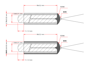
Feiyi’s dedicated single-fiber collimators list housing choices including 1.4 ×8, 1.8 ×8, 2.78 ×8 and 3.2 ×9 mm. These dimensions matter to the mounting seat, but the design also needs a defined rotational reference for polarization. Specify the relationship between the fiber axis, housing reference and the free-space element’s required orientation.
Fast-axis and slow-axis collimator choices require a defined rotational reference
The product information lists fast- and slow-axis choices. Agree which one is used and how the operator identifies it after the housing is mounted. A cylindrical body can fit at multiple rotations unless the assembly gives it a reference. Do not leave polarization alignment dependent on an undocumented technician adjustment that cannot be repeated during replacement.
For an instrument with a removable optical subassembly, distinguish the connector-axis reference from the housing-axis reference. The connector controls the incoming PM interface; the mounted collimator determines how that polarization meets the free-space optics. Both references belong in the accepted assembly drawing. A connector key by itself does not establish how the cylindrical housing has been rotated in the carrier.
The body should be retained without transmitting stress through the fiber exit. Ask the supplier for the selected component’s mounting and handling limits, then validate the intended carrier. Neither the listed housing diameter nor a successful optical measurement establishes a safe clamp force or bend radius. Keep those unsupported values out of the purchase document until they are agreed.
Keep the wavelength variant, lens construction, housing seat and rotational reference in one revision-controlled drawing. A replacement should return to an identified beam path, rather than require rediscovering the prototype’s favorable alignment.
Dual- and four-fiber PM collimators add channel geometry to the beam interface
Feiyi’s PM dual-fiber collimator and PM four-fiber collimator provide multi-fiber routes for component assemblies. Their fiber counts should be linked to the optical destinations and the approved beam geometry. More fibers do not mean that the output beams or axes automatically fit the same arrangement as a single-fiber unit.
Two PM fiber channels need their own throughput and axis records
An OEM using two optical channels in one compact assembly should identify which remote lead belongs to each optical position. Define the required axis relationship and acceptance conditions for each channel. Do not use a total collected-power reading as proof that both channels meet their individual requirements. The receiving optics must correspond to the actual channel arrangement.
The dual-fiber listing gives minimum extinction ratio of 21 dB at 23°C; the four-fiber listing gives 20 dB. These are separate product entries. If a system moves from two to four channels, reopen the applicable polarization requirement and measurement record. A family-wide statement using the highest single-fiber value would misdescribe the supplied range.
The four-fiber listing includes 2.78 ×8 and 3.2 ×9 mm housing choices. Confirm the mechanical and optical configuration together. A multi-fiber device with a suitable outer diameter may still need different channel orientation, receiving optics or lead identification from the prototype. The drawing should define these relationships before the component is bonded or retained.
Accept the PM collimator pair in the installed free-space geometry
The useful result for the opening instrument scenario is the transmitted and recoupled signal in its actual path. Record the selected emitting and receiving components, gap, intervening element, wavelength and axis reference. Then separate component acceptance from the assembled path measurement. That distinction helps determine whether a changed result arises at a connection, an optical surface or the mounting arrangement.
Measure the beam’s position as well as its size at the receiving plane. A suitably small beam can still miss the intended aperture if its pointing or mounting reference is wrong. For the PM dual-fiber arrangement, associate each position with its identified fiber lead, so the mechanical alignment does not silently exchange the two intended optical destinations.
Newport’s collimation-testing application note provides technical background for evaluating collimation rather than relying on a near-housing spot alone. Select an appropriate test with the optical engineer and define its acceptance conditions. Do not invent a measured divergence or stability claim for a Feiyi sample that has not been tested.
Request optical-end protection and packaging support appropriate to the selected lens housing and leads. At receiving, keep those surfaces protected until the mounting fixture is ready, and identify the wavelength variant before placing it in a common carrier. The packaging request should preserve the component’s optical-end cleanliness and fiber exits without implying an undocumented standard delivery method.
Feiyi’s existing PM collimator selection guide is useful background for the range. For this assembly, finish with a defined beam at the relevant planes, a receiving interface that accepts it and a mounting datum that preserves its PM orientation. Those three agreements make the working-distance request meaningful.