PM Optical Components Supplier: Turning an Engineering Schematic Into a Repeatable Order
When an engineering team searches for a PM optical components supplier, the difficult handoff is usually not finding a catalog item. It is converting an optical design into a purchase description that preserves polarization from one component to the next. A drawing may show a PM patch cord, pigtail, collimator, attenuator and switch as separate blocks, but purchasing has to know which wavelength, fiber, axis, connector, lead length and optical limits belong to every block.
Feiyi’s published product range is broad enough to make that handoff concrete. The PM portfolio includes single- and multi-fiber pigtails, collimators, patch cords, optical switches, variable optical attenuators, WDM devices, circulators, isolators, couplers, in-line polarizers and polarization beam combiner/splitters. For a buyer, that breadth is useful only when each interface is written unambiguously. The most productive supplier discussion therefore starts with the optical chain rather than a generic request for “PM components.”
A PM optical components supplier needs the same axis language as your drawing
Polarization-maintaining fiber is intentionally birefringent, so the launch orientation relative to its principal axes is part of the design. Connector keys, splice orientation and component working axis cannot be treated as cosmetic details. Feiyi’s custom PM patch cord page states that connectorized devices are keyed to the slow axis, and its ordering table allows slow- or fast-axis alignment. That is the type of detail that should move from a product page into the controlled drawing.
For a prototype lab setup, an engineer may be able to rotate a component and recover the expected extinction ratio. A production assembly cannot rely on that adjustment. The RFQ should identify the axis convention, connector polish and mating direction before cable length is frozen. This is particularly important when parts from several families are connected directly.
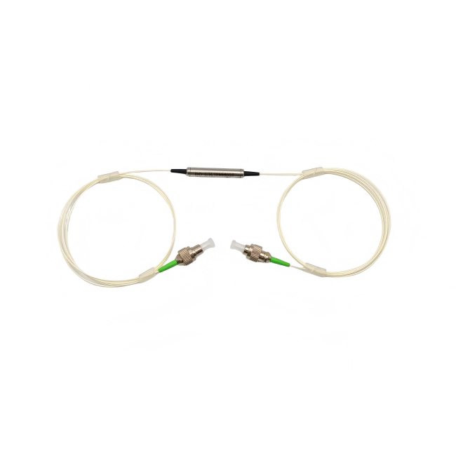
PM patch cords should carry wavelength, polish and axis on one line item
Feiyi’s PM fiber patch cord family covers 780, 850, 980, 1064, 1310 and 1550 nm. The published performance table lists extinction ratio of at least 20 dB, repeatability no greater than 0.1 dB, interchangeability no greater than 0.2 dB and at least 1,000 mating cycles. Connector options in the ordering information include FC/UPC, FC/APC, SC/UPC, SC/APC, LC/UPC and LC/APC.
A buyer should not split those choices across several emails. A practical line item might define 1550 nm, PM1550 fiber, slow-axis key alignment, FC/APC termination and the required length together. That gives the supplier a configuration to build and the receiving team a configuration to inspect. The detailed reasoning behind connector-axis alignment is also covered in Feiyi’s PM patch cord axis guide.
Single-fiber and multi-fiber PM pigtails belong to different mechanical handoffs
Feiyi publishes PM single-fiber, dual-fiber, four-fiber, five-fiber, nine-fiber and sixteen-fiber pigtails. A multi-fiber pigtail is not simply several single-fiber parts placed together. The fiber count changes routing, labeling, bend management and the way the assembly mates to the next optical element.
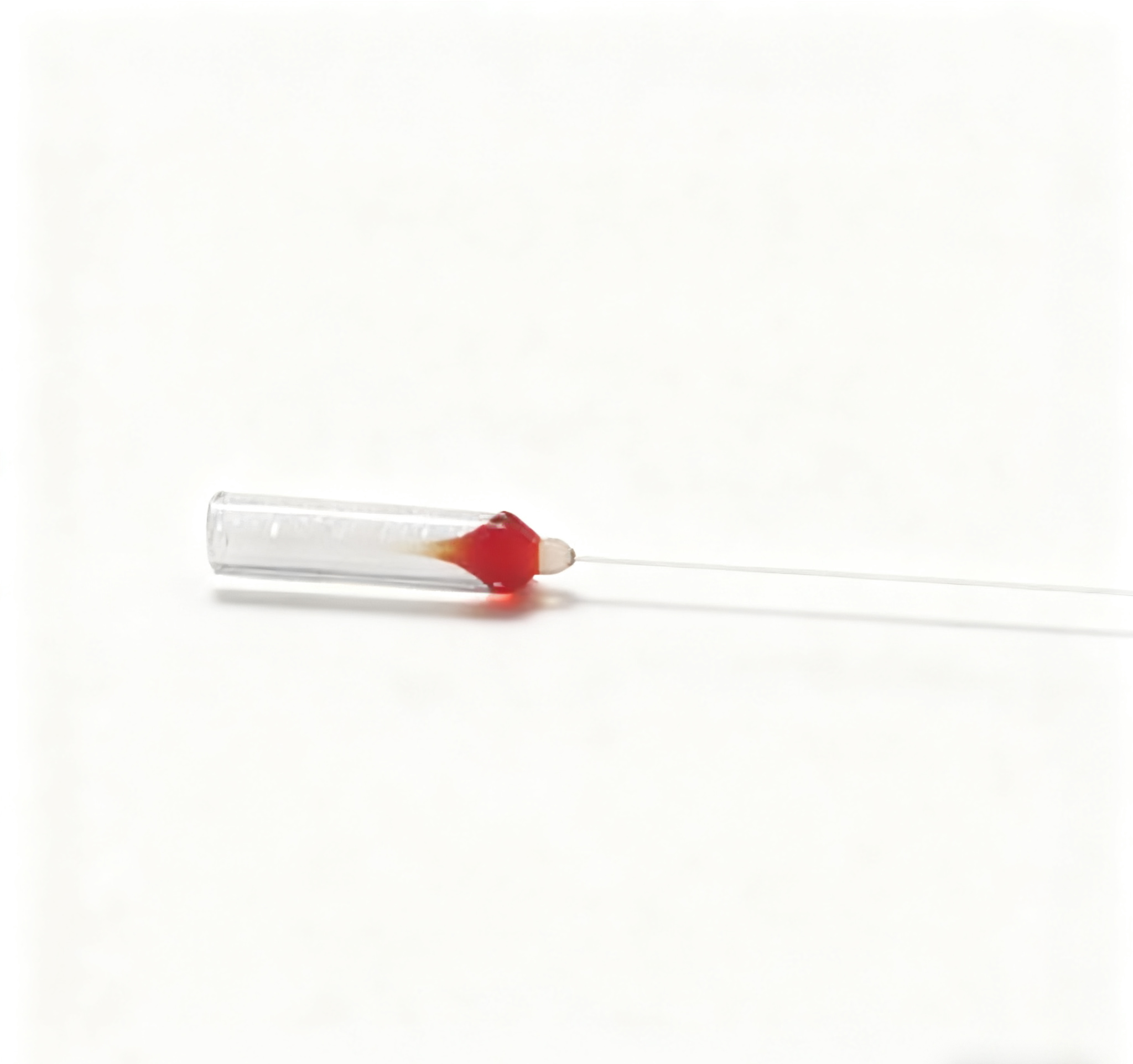
For a photonic module with several parallel channels, the handoff should state the number of fibers, target wavelength, fiber type, lead length and how fibers are identified. For a single laser input, a single-fiber PM pigtail is normally easier to route and inspect. The earlier PM pigtail assembly-interface article shows why fiber count should be resolved before packaging is finalized.
PM optical components supplier selection changes when free-space optics enter the chain
The interface becomes more demanding when a guided fiber mode is converted to a free-space beam. At that point, PM fiber orientation is only one part of the requirement. Working distance, beam diameter, fiber count and mechanical placement also matter. Feiyi’s PM collimator range includes products from 630 to 1550 nm and configurations from single-channel devices to dual-, four-, five-, nine- and sixteen-fiber units.
A PM collimator RFQ should describe the beam interface, not just the connector
A buyer sourcing a collimator for a 1064 nm laser instrument should first define the 1064 nm optical path and desired beam interface. Connector type may still matter, but it is downstream of the optical job. Multi-fiber collimators are more relevant when several channels must be launched or received in a common mechanical region; a single-fiber collimator is a better fit when the system has one beam path.
This distinction prevents a common sourcing error: selecting by housing photograph. Two cylindrical collimators can have very different optical jobs. Feiyi’s PM collimator product family and the beam-interface discussion for PM collimators are useful references when the engineering drawing still lacks working-distance or channel-count detail.
VOA placement should be tied to the detector or amplifier power range
Feiyi’s PM VOA family includes 780, 850, 980, 1064, 1310, 1550 and 2000 nm products. In a test system, a VOA may be used to prevent a detector from saturating or to sweep received optical power. In an amplifier chain, it can be used to control level between stages. The purchasing description should therefore identify where attenuation occurs and which wavelength passes through the device.
A PM VOA is not a substitute for a polarizer. Attenuation controls optical power; an in-line polarizer controls polarization content. If both are required, they should appear as separate functions in the schematic. Feiyi’s 1550 nm in-line polarizer publishes typical insertion loss of 0.3 dB and typical extinction ratio of 30 dB, while the VOA family is specified around controllable attenuation. Combining those functions conceptually is an easy way to create an incomplete RFQ.
PM component supplier decisions for switched optical paths need electrical information too
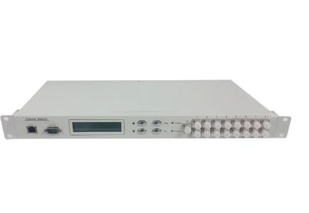
An optical switch adds an electrical state to an otherwise passive-looking optical chain. The buyer has to define not only wavelength and fiber, but also the required port topology, latching behavior, drive voltage and expected state after power removal. Feiyi’s PM switch range includes 1×2, 1×3/1×4, 2×2 and magneto-optic configurations.
The PM 1×3/1×4 switch makes route state part of the procurement specification
Feiyi’s PM 1×3/1×4 optical switch is published for 1310 or 1550 nm and also 780/850/980/1060 nm variants. The table lists crosstalk of at least 55 dB, return loss of at least 50 dB, repeatability within +/-0.05 dB, switching time of 10 ms and a rated lifetime above 1,000,000 cycles. It supports latching and non-latching operation.
Those details matter differently by application. A test instrument that changes routes frequently may care strongly about cycle life and repeatability. A fail-safe optical path may care first about what happens when drive power disappears. A laboratory multiplexer may be more concerned with connector accessibility and wavelength. The supplier cannot infer those priorities from the words “PM optical switch.”

How to turn an engineering BOM into a repeatable PM supplier order
The first order should create records that the second order can reuse. For every component, preserve the approved product family, drawing or ordering code, wavelength, fiber type, connector polish, axis convention, fiber length and the optical limits that were actually accepted. If a sample is approved with a specific connector orientation, do not let the repeat order collapse back to a generic family name.
Receiving inspection should also follow the optical role. For patch cords, confirm connector end face, axis key and insertion loss before measuring extinction ratio. For pigtails, confirm fiber count and identification before assembly. For collimators, confirm channel count and the agreed beam-interface condition. For VOAs, verify attenuation behavior over the required operating point. For switches, verify route state, drive mode and optical loss in each state.
Feiyi’s public pages provide product specifications but do not publish a single universal packing method for every PM component. That means packaging should be agreed for the specific order, particularly where bare fibers, multiple labeled leads or connector end faces need protection. The handoff should state how the receiving team expects channels and ports to be identified.
For wavelength-selective PM assemblies, the supplier handoff starts with a port map
WDM components introduce another layer of ambiguity because the same three-fiber package can represent different pass, reflect or common-port functions. Feiyi publishes polarization-maintaining filter WDM devices and PM DWDM three-port devices at several wavelength families. The public PM WDM portfolio includes 1064 nm, 1550 nm and 2000 nm variants as well as 100G/200G DWDM products. For purchasing, the safest description is not only the center wavelength. It is a small port map showing which wavelength enters the common port, which band passes, which band reflects, and which PM fiber is required on each lead.
Feiyi’s PM DWDM three-port specification publishes pass-channel insertion loss no greater than 0.8 dB, reflection-channel insertion loss no greater than 0.6 dB, isolation of at least 25 dB, minimum extinction ratio of 18 dB, PDL below 0.1 dB, directivity above 50 dB and return loss above 45 dB. The same page lists PM Panda fiber options and 300 mW maximum power handling. Those figures provide useful limits for a technical review, but they do not remove the need to define the actual wavelength map for the ordered variant.
A wavelength map prevents a PM WDM from being wired correctly but functionally wrong
Imagine a fiber amplifier subassembly where a pump wavelength and a signal wavelength share one PM path. If the buyer specifies only “PM WDM,” the supplier still has to guess which wavelength should pass, which should reflect and which fiber is used at each port. Even when all three pigtails are connected to the right physical locations, a reversed optical function can make the assembly unusable. A one-page drawing with common, pass and reflection labels is more valuable than a long verbal description.
The same principle applies when PM WDM devices connect to circulators or isolators. Each device has a directional or wavelength-selective behavior, so port naming must survive the handoff between the optical schematic and the purchase order. That is why the earlier PM WDM wavelength and port-map guide begins with routing rather than channel count.
Company capability and component acceptance should stay as two separate checks
Feiyi’s About page states that the company was established in 2014, operates production bases in Shenzhen and Shaoguan totaling about 6,000 m2, is ISO9001:2015 certified and manufactures both single-mode and PM passive components. Those facts are relevant when an overseas buyer is deciding whether to open a supplier qualification. They do not replace the sample approval for a specific PM component.
A useful qualification process therefore has two tracks. The commercial or supplier-quality team can review company identity, quality-system information and manufacturing scope. The optical engineering team can review the actual patch cord, pigtail, collimator, VOA, switch or WDM data against the design. Once both tracks are accepted, purchasing can preserve the exact approved configuration for repeat orders instead of treating every item from the same supplier as automatically interchangeable.
Choose the PM optical components supplier around the interfaces that can fail
For a new PM project, start by drawing the polarization-sensitive interfaces and marking the wavelength at each point. Then add the axis convention, connector or splice, expected optical power and the function performed at that interface. This naturally separates patch cords from pigtails, collimators from polarizers, attenuators from switches and circulators from isolators.
Feiyi’s PM portfolio can support those different functions, but the supplier still needs a project-specific definition. A well-written RFQ lets engineering, purchasing and incoming inspection talk about the same configuration. That is much more valuable than a broad request for PM parts because it reduces ambiguity before the first sample is built and gives repeat orders a controlled reference.