
PM MPO MTP Patch Cord Manufacturer: Control Channel Mapping and Polarization Together
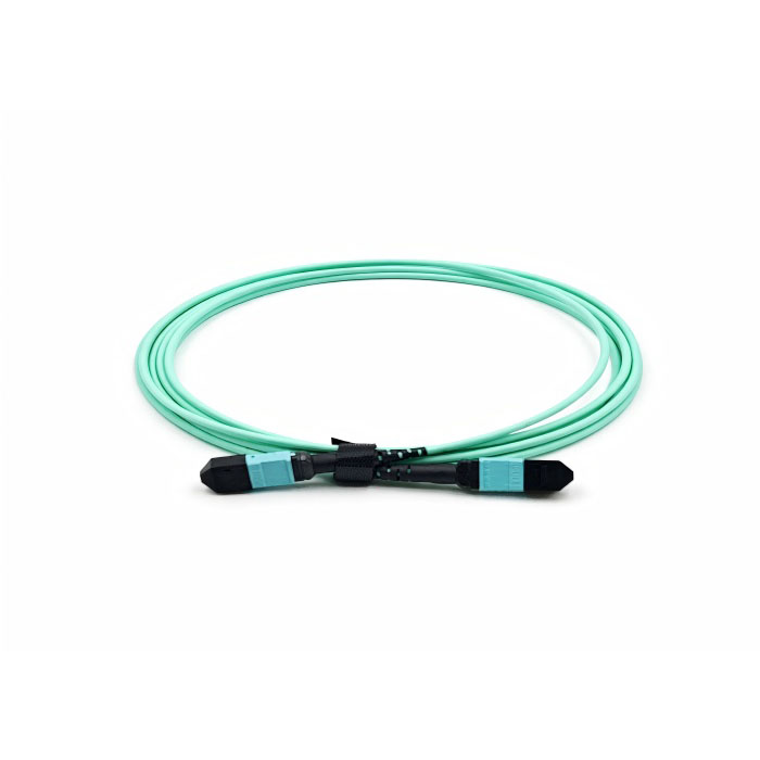
A buyer searching for a PM MPO MTP patch cord manufacturer is combining two requirements that are easy to confuse: high-density multi-fiber connectivity and preservation of polarization orientation. A standard MPO/MTP assembly is designed around multiple aligned fiber channels and a defined polarity scheme. A polarization-maintaining multi-fiber assembly adds a rotational axis requirement for each PM fiber. Before asking for price or length, the buyer should therefore define fiber count, channel mapping, connector gender/pinning, optical polarity and the required PM axis convention.
Feiyi’s website presents PM MPO-MTP patch cords as a high-density PM connectivity solution, while its published product catalog also includes standard MPO/MTP optical patch cords and single-fiber PM patch cords. Those related products give a buyer useful reference points, but they should not be collapsed into one specification. The exact PM MPO/MTP configuration should be confirmed from the project drawing and the manufacturer’s approved technical file rather than inferred from a standard MPO trunk.
A PM MPO MTP patch cord manufacturer has to control both channel position and polarization axis
A conventional multi-fiber connector must place every fiber in the correct physical position. A PM assembly must also preserve the defined orientation of the slow or fast axis for each polarization-sensitive channel. That creates two independent alignment questions. A cable can have the correct fiber sequence but the wrong PM rotational orientation, or the correct PM fiber type but the wrong end-to-end channel polarity.
Fiber count and end-to-end mapping should be frozen before axis acceptance
Feiyi’s standard MPO/MTP product family demonstrates the high-density connector format, while the company’s PM portfolio demonstrates its use of polarization-maintaining fiber and axis-aligned connectorization. For a PM MPO/MTP project, the engineering drawing should show channel 1 through the final channel at both ends of the cable, then separately state the PM axis reference for those fibers.
A parallel optical test rack may require a straight-through channel map because every source has a dedicated detector. Another assembly may deliberately cross channels to match a board or photonic package. Neither can be inferred from the cable length or connector shell. The manufacturer should receive the full channel map before production.
PM axis convention should be written independently from MPO/MTP polarity language
Feiyi’s single-fiber PM patch cord page states that connector keys on connectorized devices are aligned to the slow axis and publishes slow- and fast-axis ordering choices. That is a useful reference for understanding how explicit a PM axis convention needs to be. An MPO/MTP project should use an equivalent controlled definition suited to the multi-fiber ferrule rather than relying on a generic phrase such as “PM aligned.”
The drawing should identify which principal axis is the intended launch axis and how that axis relates to the connector reference. If the cable connects directly to another PM array, the receiving component’s axis convention must be compared at the same time. A high extinction ratio measured before mating is not enough if the mated assembly rotates the launch relative to the next component.
PM MPO MTP patch cord manufacturer selection should distinguish standard MPO requirements from PM requirements
Standard MPO/MTP patch cords are widely used where density and fast multi-channel connection matter. Their key purchasing questions include fiber count, connector format, polarity, fiber type and insertion/return loss. A PM MPO/MTP assembly inherits those questions and adds polarization-sensitive fiber and rotational alignment.
Do not copy a data-center MPO trunk specification into a PM photonics project
A standard data link may use single-mode or multimode MPO/MTP cabling without any requirement to preserve the input polarization state. A PM sensing, coherent or laboratory assembly may use the same multi-fiber mechanical concept but cannot treat fiber rotation as irrelevant. The fiber itself and its orientation become part of the optical function.
Feiyi’s standard MPO/MTP patch cord page can therefore be used to understand the connector family, but it should not be used as proof of a PM multi-fiber performance value that is not explicitly stated for the ordered PM version. The PM MPO/MTP drawing should have its own acceptance limits for insertion loss, return loss, axis alignment and any required extinction-ratio measurement.
Single-fiber PM patch cord data provides a useful polarization reference, not a multi-fiber guarantee
Feiyi’s custom PM single-fiber patch cord family covers 780, 850, 980, 1064, 1310 and 1550 nm. Its published table lists extinction ratio of at least 20 dB, repeatability no greater than 0.1 dB, interchangeability no greater than 0.2 dB and at least 1,000 mating cycles. Those are confirmed values for the published single-fiber family.
A buyer can use that page to see how Feiyi documents PM connectorization, but should not automatically transfer the same numerical limits to a PM MPO/MTP assembly. Multi-fiber ferrules introduce their own dimensional and channel-to-channel considerations. The correct approach is to ask the manufacturer to confirm the PM MPO/MTP acceptance specification for the exact configuration.
High-density PM assemblies should be designed around the device at each end
The reason for using MPO/MTP is usually not the cable itself; it is the density of the system that the cable connects. The purchasing conversation should therefore start with the transmitter, sensor array, photonic module or test fixture at both ends. The cable needs to reproduce those channel positions and polarization references.
A multi-channel PM sensor rack needs labeling that survives installation
Consider a rack containing several polarization-sensitive sources and detectors. The integrator may choose a single multi-fiber connector to reduce front-panel space and cable handling. During installation, a technician needs to know which channel reaches which instrument. During replacement, the service team also needs to preserve the original mapping.
The cable drawing should therefore include channel numbering, end identification and orientation markers that remain visible after installation. Inner packaging should use the same product identifier as the drawing. The website does not state one universal Feiyi packing scheme for every PM MPO/MTP order, so labeling and packaging requirements should be agreed for the actual project.
A PM fiber array interface may need a fanout rather than MPO/MTP at both ends
Some high-density systems use a multi-fiber connector at the rack interface but individual PM connectors or bare-fiber leads at the optical module. In that case, the buyer is not purchasing a simple trunk. The fanout length, channel labels, connector types and axis references on the individual legs become part of the assembly.
Feiyi’s broader PM portfolio includes single- and multi-fiber pigtails, PM collimators and PM patch cords. Those families can help the engineering team decide where a multi-fiber connector is mechanically useful and where individual PM leads are easier to align or service. A dense connector should not be forced into an interface that needs separate optical adjustment per channel.
When a PM MPO/MTP patch cord is the wrong mechanical choice
High density is valuable only when it simplifies the complete assembly. If each PM channel needs independent angular adjustment, separate connector access or different fiber lengths, a common multi-fiber ferrule can make integration harder rather than easier. In that case, individual PM patch cords or a labeled fanout may give the optical engineer more control.
Prototype benches often benefit from individual PM connectors first
During early development, engineers may need to swap one channel, rotate a launch condition, compare connector polish or insert a VOA into only one path. Individual FC/APC or other keyed PM interfaces make those experiments easier to isolate. Once the channel arrangement is stable and the mechanical envelope becomes the dominant constraint, the design can be consolidated into a high-density multi-fiber assembly.
This staged approach also produces better manufacturing information. The team learns which wavelengths, lengths and axis conventions actually work before asking a manufacturer to place several channels into one connector. The PM MPO/MTP drawing can then be derived from a proven bench configuration instead of becoming an additional unknown during optical development.
Serviceable field links may favor a fanout where only one channel is replaced
A field system can also lose some of the service advantage of high density if one damaged channel forces replacement of the entire multi-fiber cable. Where individual channel replacement matters, a hybrid assembly with MPO/MTP on the dense equipment side and separate PM leads on the service side may be more practical. The decision depends on the failure and maintenance model, not only on front-panel space.
For distributors and OEM buyers, this is a useful question to resolve before quotation: is the objective maximum connector density, simplified installation, or independent channel service? The same PM fiber technology can be packaged differently depending on which of those objectives matters most.
Acceptance testing should check channel identity before polarization performance
A practical incoming sequence begins with inspection and channel mapping. Confirm the connector shells, orientation, fiber count and end identification. Verify that each input channel reaches the intended output channel. Only then move into insertion-loss and polarization measurements. If channel mapping is wrong, later optical measurements can be misinterpreted because the wrong source and detector are being compared.
Insertion loss should be recorded per channel rather than as one cable value
A multi-fiber assembly contains several optical paths. Recording a single average can hide an outlier. For an engineering sample, preserve results by channel so the team can see whether one position behaves differently from the rest. The manufacturer and buyer should agree the measurement wavelength and connector cleaning procedure so repeat tests are comparable.
If the PM requirement includes extinction ratio or axis-angle acceptance, that measurement should also be defined per relevant channel. Fiber stress from routing can affect polarization performance, so the test fixture should avoid uncontrolled bends or twisting that would make a cable appear worse or better than it will be in the final installation.
Mating-cycle expectations should reflect how the assembly is actually serviced
A laboratory fixture disconnected several times each day faces a different mechanical duty from an internal harness that is installed once. Feiyi’s published single-fiber PM patch cord specifies at least 1,000 mating cycles, but a buyer should confirm the applicable requirement for the exact PM MPO/MTP product rather than assume that single-fiber figure transfers directly.
The procurement file should record whether the connector is a service interface or a permanent internal connection. That information helps the manufacturer and integrator discuss ferrule protection, cleaning access and replacement strategy realistically.
A PM MPO/MTP order needs a drawing detailed enough to reproduce the approved sample
After sample approval, preserve the cable length, PM fiber type, channel count, connector definition, polarity map, axis convention, channel labels and test limits in one controlled document. If one end uses a fanout, include the breakout length and individual connector or bare-fiber definition. If the assembly has orientation-sensitive housings, show the viewing direction used in the channel map.
Useful Feiyi references include the MPO/MTP patch cord range, the PM fiber patch cord family and the company’s PM axis-alignment guide. The PM engineering-handoff article is also useful when the multi-fiber cable is only one part of a larger polarization-sensitive assembly.
The safest PM MPO/MTP sourcing decision is one where density, channel mapping and polarization alignment are all visible before production begins. A short phrase such as “12-fiber PM MPO cable” cannot capture those requirements. A controlled drawing can.