PM Beam Combiner Manufacturer: Separate Polarization Routing From Wavelength and Power Splitting
A buyer searching for a PM beam combiner manufacturer should begin by defining what is being combined: two orthogonal polarization states, two physical ports, or two optical wavelengths. Those are different optical jobs. Feiyi’s polarization beam combiner/splitter family is intended for polarization routing and is published in 1×2 and 2×2 formats across several PM wavelength families. It should not be confused with a WDM, which separates wavelengths, or a conventional coupler, which divides or combines optical power.
Feiyi lists PM beam combiner/splitter products at 780, 850, 980, 1064, 1310, 1480, 1550 and 1950 nm in its current catalog. That range is useful for laser, sensing and coherent optical projects, but the wavelength alone does not select the device. The buyer still needs to define port function, polarization state, working axis, fiber type, connectorization and power.
A PM beam combiner manufacturer needs the polarization diagram before the purchase order
A polarization beam combiner/splitter routes light according to polarization. In a combining use, two polarization states can be brought into a common output path. In a splitting use, the device separates polarization components into different ports. The schematic should show those states explicitly because “1×2” or “2×2” only describes port count, not the intended polarization direction.
1×2 PM beam combiner/splitter suits a simple common-port polarization interface
Feiyi publishes 1×2 products across multiple wavelengths, including a PM 1550 nm 1×2 Polarization Beam Combiner/Splitter. Its current product page lists 1550 nm operation with a +/-40 nm range, typical insertion loss of 0.4 dB and maximum insertion loss of 0.6 dB. The page also publishes return loss of 50 dB and a minimum extinction ratio of 22 dB at 23 deg C for the PM fiber type.
The same page identifies SM-28E or PM1550-XP input/output fiber options and slow-axis operation with fast-axis cutoff. Fiber length is listed as at least 1 m at each end, and power options on the ordering table include 0.3, 1, 2, 5 and 10 W. For a buyer, those figures are more useful than a generic claim of “high extinction ratio” because they can be tied to a specific 1550 nm configuration.
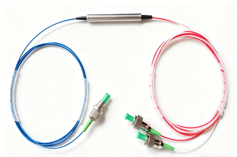
2×2 PM beam combiner/splitter adds another route and a different loss budget
Feiyi’s PM 1550 nm 2×2 Polarization Beam Combiner/Splitter page lists the same 1550 +/-40 nm operating range but publishes typical insertion loss of 0.6 dB and maximum insertion loss of 1.0 dB. Return loss is 50 dB and the minimum extinction ratio is listed as 20 dB at 23 deg C for the PM fiber type.
That makes the 2×2 configuration a different engineering choice rather than simply a larger 1×2 part. A system that needs access to two polarization-related paths may justify the additional port structure. A design that needs only one common output should not accept the extra topology without understanding how it affects routing, insertion loss and packaging.
PM beam combiner manufacturer selection should distinguish polarization from wavelength combining
PM WDM products and polarization beam combiners can both appear in laser systems, and both may have three fiber leads. Their selection logic is not the same. A WDM separates or combines different wavelengths. A polarization beam combiner separates or combines orthogonal polarization content. If the project has two lasers at different wavelengths, a WDM question comes first. If the project has polarization states that must share or separate a path, the polarization combiner is the relevant family.
A dual-wavelength laser assembly may need WDM and PM beam combining as two separate stages
Consider a system containing two wavelengths and a polarization-sensitive downstream element. A WDM can manage the two wavelengths while a PM beam combiner manages polarization states. Replacing both functions with one vaguely specified “combiner” invites the wrong component. The engineering drawing should identify whether each port distinction is based on wavelength or polarization.
Feiyi’s PM WDM range includes filter WDM and three-port DWDM products, while the PM beam combiner/splitter family has dedicated 1×2 and 2×2 products. Using separate product-family names in the BOM keeps the optical roles visible to purchasing and incoming inspection.
A conventional PM coupler is also not the same as a polarization beam combiner
Feiyi’s PM coupler range includes 780/808/850 nm and 980/1030/1064 nm 1×2 and 2×2 couplers as well as a 1310/1550 nm 1×3 product. A coupler is selected around optical power division or combination. A polarization beam combiner is selected around polarization-state routing. They may share PM fiber and similar connector options, but the project purpose is different.
If the requirement says “50/50 split,” the engineer should first determine whether it means an optical power ratio or two orthogonal polarization states. That one clarification can prevent a quotation from the wrong product family.
Working axis and connector definition are part of PM beam combiner performance
The published 1550 nm beam combiner/splitter pages state slow-axis operation and fast-axis cutoff. That information should be carried into the purchase drawing. If the device is connectorized, the buyer also needs to define how the connector key represents the PM axis and whether UPC or APC polish is required.
The adjacent PM patch cord must use a compatible axis convention
Feiyi’s PM patch cord family publishes a slow-axis key convention for connectorized devices and covers 780, 850, 980, 1064, 1310 and 1550 nm. When a PM patch cord connects directly to a beam combiner, both sides should be reviewed together. A correct beam combiner cannot recover polarization purity that was lost because the launch into its PM pigtail used the wrong axis.
For a production fixture, capture the connector orientation in the drawing rather than relying on assembly experience. This gives the manufacturer, cable supplier and receiving team the same reference and reduces the chance of a 90-degree rotational error.
Power handling should be specified from the real laser path
The 1550 nm 1×2 and 2×2 product pages list ordering options for 0.3 W, 1 W, 2 W, 5 W and 10 W average power. A buyer should select the applicable range from the actual optical system and confirm the ordered configuration with the manufacturer. It is not enough to know the source’s nominal output if amplification or combining increases power at the component.
A laboratory source and a high-power fiber system may need the same wavelength but different construction
A low-power coherent test setup may prioritize insertion loss and extinction ratio. A higher-power laser assembly may make power capability the first screening condition. Both can operate at 1550 nm, so wavelength alone does not distinguish them. The RFQ should state expected continuous or average optical power at the combiner location and any margin required by the project.
If the beam combiner sits after another combining stage or amplifier, use the power at the device rather than the laser nameplate at the source. This keeps the specification tied to the real optical chain.
Wavelength coverage lets one PM beam combiner manufacturer support different optical platforms
Feiyi’s catalog lists polarization beam combiner/splitter products at 780, 850, 980, 1064, 1310, 1480, 1550 and 1950 nm. That range matters when an OEM develops several instruments around different laser technologies. The same purchasing logic can be reused鈥攄efine polarization route, axis, fiber, connector and power鈥攂ut the actual component still has to be approved for its own wavelength family.
Near-infrared laser projects should not inherit 1550 nm assumptions
A 980 or 1064 nm laser instrument may use different PM fiber, source power and connector environment from a 1550 nm communication or sensing system. Even when the part name is the same, the surrounding optical chain changes. Buyers should therefore request the published 980 or 1064 nm product information and keep it under a separate controlled part number.
This is particularly important when an engineering team copies an earlier 1550 nm drawing to accelerate a new product. Connector type and mechanical package might remain similar, but fiber selection, wavelength tolerance and optical test source must be updated. A manufacturer’s broad wavelength range is useful because it provides a family path, not because one part can be treated as universal.
1310, 1480 and 1950 nm projects need the same discipline for different reasons
At 1310 nm, a buyer may be integrating with communication or sensing components already available in that band. Around 1480 nm, the surrounding assembly may involve pump or amplifier functions. Near 1950 nm, the optical source, fiber and detector environment can be very different from conventional telecom hardware. The beam combiner’s role remains polarization routing, but the qualification setup has to match the real wavelength.
For a multi-product OEM, it is useful to keep a common drawing format across those families. Put the wavelength in a dedicated field, show the same port-view convention, state the PM axis in the same location and record power and connector choices consistently. That makes internal design reviews faster while preventing the manufacturing file for one wavelength from being accidentally reused for another.
Incoming inspection should verify port identity before optical polarization measurements
A 1×2 or 2×2 device needs clear port labels and an agreed route diagram. Start incoming inspection by checking the ordered wavelength, fiber and connector configuration, then verify port identity. After that, measure insertion loss and the polarization behavior relevant to the approved specification using the same axis reference defined in the drawing.
Fiber handling matters during the test. Sharp bends or uncontrolled twisting can affect PM measurements. Connector end faces should be inspected and cleaned before loss or extinction-ratio testing. If the device is bare fiber, the launch and splice method should be documented so repeat measurements can be compared.
Feiyi’s public pages do not publish one universal packing method for all beam combiner variants. For repeat OEM orders, agree how multiple leads will be identified and protected, especially when a 2×2 device contains several visually similar fibers.
Choose between 1×2, 2×2, WDM and coupler by the variable being routed
If the project needs one polarization common port, start with the PM 1550 nm 1×2 beam combiner/splitter or the corresponding wavelength family. If it needs a two-by-two polarization route, compare the PM 1550 nm 2×2 version. If the variable is wavelength, move to the PM WDM range. If the goal is power division, compare PM optical couplers.
The earlier PM coupler article focuses on power split decisions, while the PM WDM guide focuses on wavelength routing. A beam-combiner order should remain centered on polarization. Keeping those three variables separate gives the manufacturer a much cleaner specification and gives the buyer an acceptance test that matches the actual optical job.