AWG Module Supplier: Decide Flat-Top vs Gaussian Before Freezing a 40/48-Channel Build
An AWG module supplier becomes relevant when a network designer has moved beyond a few discrete wavelength filters and needs a repeatable multi-channel device with a known spectral shape. At that point, “40 or 48 channels” is only the beginning. The buyer must decide the channel plan, 100 GHz spacing, flat-top or Gaussian passband behavior, insertion-loss allowance, isolation, connector interface and the physical module that will fit the shelf.
Feiyi’s 40CH/48CH AWG Module publishes both flat-top and Gaussian specifications in the C-band, while its athermal AWG range includes 17CH 150G, 40CH 100G, 48CH 100G and 96CH 50G products. For a system integrator, these families create two separate decisions: first choose the optical response that fits the transmitters, then choose the module and channel count that fit the equipment.
An AWG module supplier should ask whether the receiver needs flat-top or Gaussian channels
The passband shape controls how insertion loss changes as a transmitter moves away from the nominal channel center. A Gaussian response can have lower loss at the center but narrows more quickly toward the edges. A flat-top response is designed to keep a wider usable region near the center, which can be valuable when source drift or spectral width consumes more of the channel window.
Feiyi publishes different bandwidth figures for flat-top and Gaussian AWG modules
For the 40CH/48CH AWG Module, Feiyi lists a 1 dB bandwidth of 0.38 nm for the flat-top specification and 0.20 nm for the Gaussian specification. The listed 3 dB bandwidths are 0.58 nm and 0.38 nm respectively. These are not interchangeable descriptions of one filter shape.
A buyer using fixed, well-controlled transmitters may accept a narrower Gaussian profile if its center loss and system budget fit. A network where transmitter wavelength can vary within a wider range may prefer the additional flat-top margin. The correct choice comes from the source spectrum and permitted drift, not from a general assumption that one profile is always superior.
Center insertion loss and passband insertion loss should be reviewed separately
The same Feiyi page lists optical insertion loss at the ITU channel center with a typical 4.2 dB and maximum 5.0 dB for the flat-top specification, compared with typical 2.0 dB and maximum 3.0 dB for the Gaussian specification. Across the passband, the listed maximum values are 5.5 dB for flat-top and 4.5 dB for Gaussian.
This is a useful example of why a single “AWG loss” number is incomplete. A receiver sees the loss at the transmitter’s actual wavelength, not necessarily the nominal center. The acceptance document should therefore state whether the limit applies at center, across a defined passband, or at selected offset frequencies.
The AWG module supplier needs the exact channel list, not only “C-band”
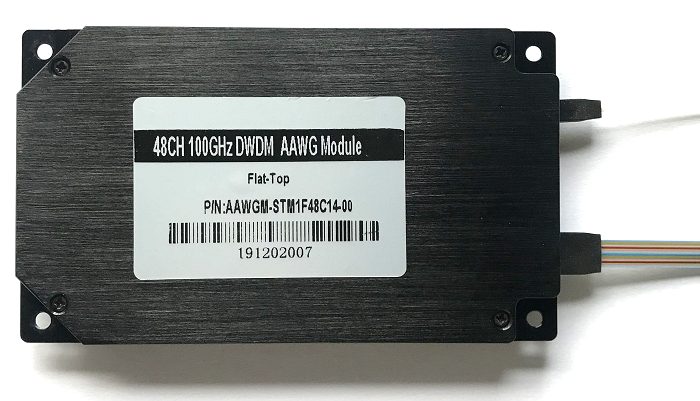
Feiyi’s 40CH/48CH AWG Module page lists 48 channels from C13 to C60 or a customized channel plan, with 100 GHz channel spacing and C-band operation. A project may use all channels or only a defined subset. The supplier needs to know which outputs are populated and how they will be labeled.
Port numbering should match the network’s channel naming convention
A forty-eight-fiber output bundle becomes difficult to service if the manufacturing label and network record use different identifiers. The project should decide whether ports are labeled by ITU channel number, frequency, wavelength or an internal port index, and then retain that mapping through the drawing, test report and field documentation.
A data-center interconnect team may care most about aligning each front-panel port with a transceiver assignment. An equipment OEM may route fibers internally and care more about fan-out length and sequence. Both use the same AWG function, but their handoff requirements are different.
Custom channel subsets should remain traceable to the full grid
If only part of the C-band is required, the purchase description should still identify the parent grid. “24 channels” is ambiguous if the manufacturer does not know which 24. A controlled list prevents a later repeat order from shifting the subset or reversing the physical output order.
ITU-T G.694.1 provides the DWDM frequency-grid framework. Use the selected grid values in the engineering file, while treating Feiyi’s product page as the source for the actual component specifications and available configurations.
AWG module supplier evaluation should include isolation and channel uniformity
Dense-channel devices must do more than pass the desired wavelength. They must keep neighboring channels sufficiently separated and avoid creating excessive power imbalance across outputs.
Adjacent and non-adjacent isolation describe different interference paths
Feiyi’s 40CH/48CH AWG Module lists adjacent-channel isolation of at least 25 dB, with typical values of 28 dB for flat-top and 29 dB for Gaussian. Non-adjacent isolation is listed at least 30 dB, with typical values of 35 and 36 dB respectively. The page also lists total crosstalk at 21 dB.
A receiver exposed to a strong immediately neighboring channel should be evaluated using the adjacent figure. A receiver concerned with aggregate leakage from many other channels has a different condition. The engineering team should identify which case limits performance instead of accepting a generic statement that isolation is “high.”
Uniformity matters when receivers share a common launch-power plan
Feiyi lists insertion-loss uniformity up to 1.5 dB for both spectral-profile options. That means a network designer cannot assume every channel has exactly the same loss even when the transmitters are launched at the same power.
For a system with automatic power control, some variation may be handled elsewhere. For a passive link with fixed transmitter and receiver settings, the worst-channel budget becomes more important. Incoming inspection can therefore sample the channel extremes and any channels known to be critical rather than measuring only one convenient center port.
Polarization effects belong in the AWG module budget even when the network is not PM fiber
Feiyi’s 40CH/48CH AWG Module lists polarization-dependent loss with a typical value of 0.2 dB and a maximum of 0.5 dB, plus polarization-mode dispersion up to 0.5 ps. These parameters describe how the device responds to varying polarization states in standard single-mode transmission.
Low PDL is not the same as polarization-maintaining operation
A network engineer should not confuse a low-PDL AWG with a PM component. The AWG module is designed so its loss changes only within the published PDL limit as polarization varies, but it does not establish or preserve a specific fast/slow axis in the way a polarization-maintaining component does.
If a project truly needs PM behavior, use Feiyi’s polarization-maintaining component families for the relevant optical function and specify the axis convention explicitly. If the project uses ordinary single-mode transmission, include PDL and PMD in the performance review without adding unnecessary PM interfaces.
Return loss and directivity should be checked with the installed connector system
The module page lists return loss of 40 dB and directivity of 45 dB. Connectorized assemblies add their own interfaces, so end-face condition and connector polish can influence the measured installed path. Clean and inspect connectors before comparing incoming results with the product specification.
A failed return-loss measurement should not immediately be attributed to the AWG chip. The test lead, adapter and connector end faces need to be controlled first. That is especially important on a high-port-count module where repeated mating can introduce contamination during commissioning.
Module packaging should be treated as part of the AWG supplier drawing
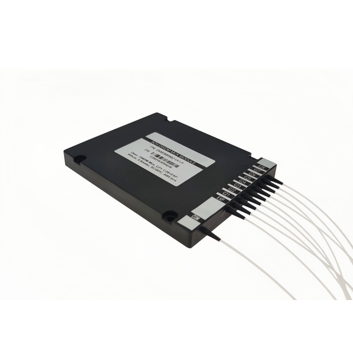
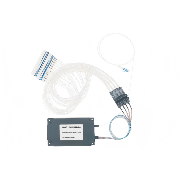
Feiyi’s 40CH/48CH AWG Module lists a 120 x 70 x 10 mm package, SMF-28e or customized fiber and LC/APC in the displayed specification. Those details define how the module enters a system mechanically, but a project may require another interface or an athermal AWG product with a different package.
Fiber fan-out length can become the limiting integration dimension
A high-density AWG may fit easily as a metal package while the forty or forty-eight fibers do not. The equipment drawing should reserve routing radius, strain relief and connector access. If output fibers must reach a front panel, their length and sequence should be approved before production.
An OEM that tested a loose prototype on a bench should repeat the optical check after the fibers are routed in the intended enclosure. Excessive bending or uncontrolled cable pressure can create a system-level loss change even when the AWG itself meets its datasheet.

A connectorized module needs a port map that survives servicing
LC/APC interfaces are compact enough for dense arrangements, but the project still needs a clear mapping from connector position to wavelength. If the module is later installed in a rack or subassembly, front-panel numbering should preserve the same identity used on the acceptance record.
For distributors, this also reduces return errors. Two 48-channel AWG modules can look similar while carrying different channel subsets or connector arrangements. The stock record should include the optical grid and physical interface, not only the channel count.
An AWG module supplier should help the buyer decide when AWG is unnecessary
Feiyi also offers 4-, 8- and 16-channel DWDM modules based on a different filter architecture. A lower-channel-count project may be simpler with those products, especially when LGX, OADM or rackmount packaging is already defined around the existing network.
Eight DWDM channels and forty-eight AWG channels are different integration problems
An 8-channel DWDM module can have lower complexity in a system that only needs a handful of wavelengths. Feiyi’s standard DWDM Module publishes 100/200 GHz options and channel counts up to sixteen, with module and rack formats. Moving such a design to a 48-channel AWG should have an engineering reason, such as actual port growth or a high-density fixed grid.
Conversely, building forty or forty-eight channels from many discrete filtering stages can complicate packaging and consistency. That is where the AWG architecture becomes attractive. The choice should follow channel count, spectral requirements and mechanical integration rather than a blanket preference.
Production approval should compare the AWG module to the transmitter set it will actually carry
Before releasing the order, provide the supplier with the exact channel list, 100 GHz spacing requirement, selected spectral profile, passband criterion, insertion-loss limit, allowed uniformity, isolation limits, connector interface and output labeling convention. If the application uses only a subset of channels, identify those channels explicitly.
At receiving, verify the physical channel map first. Then measure insertion loss on the agreed channels, check representative adjacent-channel isolation and confirm connector/end-face condition. For a module destined for an OEM enclosure, repeat a system-level optical check after final fiber routing so integration stress is not confused with manufacturing variation.
Useful Feiyi references are the 40CH/48CH AWG Module, 40-CH 100G Athermal AWG, 48-CH 100G Athermal AWG, 96-CH 50G Athermal AWG and the DWDM Module.
The useful question for the supplier is not simply “Can you supply 48 channels?” It is whether the module’s channel grid, spectral profile, loss distribution and physical port map match the transmitter shelf that will be connected to it. Once those details are frozen, repeat orders become much easier to verify.
A spare AWG module should be matched by grid and passband profile, not by port count
A maintenance team may find a forty-eight-port spare that physically fits the shelf but uses a different channel subset or spectral profile. Before treating it as interchangeable, compare the channel map, spacing, flat-top or Gaussian requirement, connector orientation and accepted insertion-loss limits. The spare record should point to the same approved drawing as the installed module so emergency replacement does not introduce a silent wavelength mismatch.