Athermal AWG Manufacturer: Qualify Channel Stability Before High-Density Deployment
When an optical network has dozens of fixed wavelengths, an athermal AWG manufacturer is not being asked to supply “a bigger WDM.” The real job is to keep many narrow channels aligned to the intended wavelength grid while the device operates across the specified temperature range, without relying on active temperature-control electronics. That makes channel plan, spectral profile, wavelength accuracy, insertion loss, adjacent-channel isolation and mechanical packaging part of one approval decision.
Feiyi publishes several athermal arrayed waveguide grating products: 17-CH 150G Athermal AWG for O-band applications, 40-CH 100G and 48-CH 100G Athermal AWG products in the C-band, and a 96-CH 50G Athermal AWG. A buyer should begin with the network band and channel spacing, then decide how many ports the system needs and what passband shape the transmitter spectrum can tolerate.
An athermal AWG manufacturer should be selected from the channel plan, not the channel count alone
AWG devices use an arrayed waveguide structure to separate or combine wavelength channels. The attraction in a dense system is the ability to handle many regularly spaced channels in one optical architecture. The risk is that a project can look compatible because the number of ports matches while the center frequencies, spacing or passband do not.
O-band and C-band AWGs belong to different optical platforms
Feiyi’s 17-CH 150G Athermal AWG is described for O-band WDM applications and uses a 150 GHz channel-spacing concept. Its product page lists operation without external temperature-control power and an environmental range from -40 to +85 degrees Celsius. That product should be discussed with systems whose transmitters and receivers are already designed around the O-band.
The 40-CH and 48-CH 100G Athermal AWG products instead target the C-band. The 48-channel page lists ITU-grid frequencies across a published 191.7 to 196.4 THz range, while the 40-channel product is likewise positioned for C-band DWDM transmission. An engineer cannot move a design from O-band to C-band by changing only the channel count.
50, 100 and 150 GHz spacing changes the filter window around every transmitter
Feiyi’s catalog includes a 96-CH 50G Athermal AWG, 40/48-channel 100G AAWG products and the 17-channel 150G O-band product. Tighter channel spacing allows more wavelengths in a band but leaves less spectral room between channels. The transmitter center frequency and occupied spectrum therefore become increasingly important as spacing narrows.
ITU-T G.694.1 provides the dense wavelength frequency-grid context for C-band channel planning. A buyer should provide the exact channel identifiers or frequencies rather than write “96-channel DWDM” and leave the manufacturer to infer the grid. The same discipline applies to any custom subset of a larger channel plan.
Thermal stability is the defining procurement issue for an athermal AWG manufacturer
An athermal design is intended to reduce wavelength movement as temperature changes without an external heater/controller maintaining the optical chip at a fixed setpoint. That simplifies field integration, but it does not make temperature irrelevant. The manufacturer still needs to publish and control the spectral behavior over the required environment.
Center-wavelength stability must be separated from insertion-loss stability
Feiyi’s 40-CH 100G Athermal AWG page lists wavelength stability of plus or minus 0.005 nm and an operating-temperature range from -5 to +65 degrees Celsius, with storage from -40 to +85 degrees Celsius. The 48-CH 100G page lists an operating and storage temperature range from -40 to +85 degrees Celsius and center-wavelength accuracy of plus or minus 0.05 nm.
These are different specifications and should not be collapsed into a single statement such as “thermally stable.” One tells the buyer how the spectral position is controlled; another defines the environmental range of the product. The project acceptance plan should identify which spectral measurements need to be checked at room temperature and which environmental conditions require qualification.
Athermal does not mean every channel has identical loss
The 40-CH 100G Athermal AWG page lists optical insertion loss at the ITU grid with a typical value of 4.5 dB and a maximum of 6 dB, plus insertion-loss uniformity up to 1.5 dB. The 48-CH product also lists up to 5.5 dB insertion loss at center wavelength and up to 6 dB across the full bandwidth, with uniformity up to 1.5 dB.
A network designer should therefore budget both absolute loss and channel-to-channel variation. In a multi-receiver system, the worst channel can determine required transmitter power or receiver margin even when the average channel looks comfortable.
Passband width should match the transmitter before the athermal AWG manufacturer freezes the design
A dense-channel filter is not a set of infinitely thin wavelength lines. Every channel has a usable passband, and the transmitter spectrum must remain within that window. Feiyi’s published AAWG data gives several bandwidth measurements that help an engineer judge this fit.
The 40-CH 100G AAWG publishes different widths at 1 dB and 3 dB
Feiyi’s 40-channel page lists a -1 dB channel bandwidth of 0.4 nm and a -3 dB channel bandwidth of 0.24 nm in its displayed specification. Because bandwidth notation and table formatting can be interpreted differently across device families, the buyer should reference the exact accepted datasheet and test definition rather than transfer a number from another AWG model.
The more important procurement habit is to state which bandwidth criterion matters to the system. A transmitter that drifts near the passband edge can experience more loss than the center-wavelength measurement suggests. If the application has strict power flatness requirements, request the spectral trace or defined passband acceptance that matches the project.
The 48-CH 100G AAWG gives a separate center-accuracy and bandwidth view
The 48-channel product lists center-wavelength accuracy within plus or minus 0.05 nm, a minimum 1 dB bandwidth of 0.32 nm, a minimum 3 dB bandwidth of 0.58 nm and a maximum 20 dB bandwidth of 1.2 nm. These values describe different parts of the channel shape. They should be read together rather than reduced to “100 GHz AWG.”
An OEM qualifying an AWG for a transceiver shelf should compare the transmitter spectrum with the 1 dB region first, then review adjacent-channel isolation and the wider skirts for crosstalk. A single insertion-loss point does not describe how the channel behaves across frequency.
Adjacent-channel isolation decides how much neighboring traffic reaches the wrong port
Dense channel spacing makes rejection of neighboring wavelengths a central design issue. Feiyi’s 40-CH 100G page lists adjacent isolation of at least 25 dB and non-adjacent isolation of at least 29 dB, with total-channel isolation of at least 22 dB. The 48-CH 100G page lists adjacent isolation of at least 27 dB with a typical 30 dB, and non-adjacent isolation of at least 30 dB with a typical 35 dB.
Use the minimum isolation figure when calculating receiver risk
Typical values help describe expected performance, but a production link budget should be built around the guaranteed or minimum value stated for the ordered configuration. If a receiver can tolerate only a certain level of neighboring-channel leakage, the acceptance criterion should be written against that requirement.
A data-center or metro-network buyer may have some wavelengths operating at higher launch power than others. In that case, the strongest neighboring channel can be more important than the average crosstalk across the grid. The test plan should identify the channels that create the worst credible condition.
Return loss, PDL and PMD complete the optical interface
Feiyi’s 48-CH 100G AAWG lists return loss of 40 dB, polarization-dependent loss up to 0.5 dB and polarization-mode dispersion up to 0.5 ps. The 40-channel page publishes the same maximum PDL and PMD values in its specification. These parameters can matter when the AWG sits in a link whose modulation format or receiver is sensitive to polarization effects.
They should not be confused with a polarization-maintaining component. A standard AAWG can have low PDL without preserving a defined PM fiber axis. If the project requires polarization preservation, the buyer needs to specify that system requirement separately rather than infer it from a low-PDL value.
Mechanical integration should be reviewed before approving the athermal AWG manufacturer sample
High-channel-count devices bring many output fibers into one assembly. The optical design may pass every bench test yet still be difficult to install if lead lengths, connector density or package dimensions conflict with the enclosure.
The 48-channel package has a different installation problem from a compact three-port filter
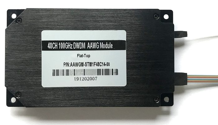
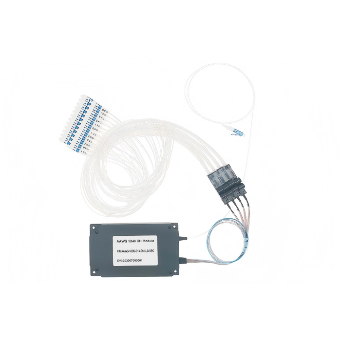
Feiyi’s 48-CH 100G Athermal AWG page lists a typical physical size of 80 x 40 x 9 mm, with an input fiber length around 900 mm and output fibers around 1000 mm in the published physical parameters. The 40-CH product lists a 120 x 70 x 10 mm package in its generic specification. The buyer should use the exact model drawing because the two pages do not describe one universal housing.
In an OEM shelf, forty or forty-eight output fibers require routing space and strain relief. A cable-management decision made after the optical sample is approved can introduce bends or connector crowding that were not present during bench testing.
Connector choice should be frozen with the channel identification method
The AWG module family can be supplied with connectorized outputs. Feiyi’s 40/48CH AWG Module page lists LC/APC in its displayed specification, while other product ordering information may support different configurations. For a high-port-count assembly, the port-label scheme must be as controlled as the connector type.
A field technician should be able to match the physical output to the documented ITU channel without tracing dozens of fibers manually. Numbering, labeling and any fan-out arrangement should therefore be included in the approval drawing.
Athermal AWG manufacturer evaluation should distinguish AAWG from a conventional DWDM module
Feiyi also publishes thin-film DWDM modules in 4-, 8- and 16-channel configurations. Those products can be a better fit when the channel count is lower or when an OADM/rack format is the main requirement. The existence of a high-channel-count AWG does not make it the automatic choice for every dense wavelength link.
Use the simplest architecture that meets the channel and spectral requirement
An 8-channel system with standard 100/200 GHz DWDM filters may not gain anything from moving to a 40-channel AWG architecture. Conversely, a 48-channel fixed plan may be much easier to package and document with an AWG than with a large cascade of individual thin-film filters.
The engineering handoff should compare channel count, insertion loss, passband, isolation, physical size and service strategy. Technology choice comes from those constraints, not from a preference for one acronym.
Approve the AAWG against a reproducible channel test
Before production, provide the manufacturer with the channel list, spacing, band, passband criterion, maximum insertion loss, uniformity requirement, adjacent/non-adjacent isolation limits, package and connector interface. For a subset of a larger grid, identify exactly which channels are populated.
Incoming inspection should use the same channel identifiers and test wavelengths as the approved file. Record insertion loss by channel, verify selected isolation points and inspect the physical port mapping. Where environmental qualification is required, define the temperature points and stabilization method rather than relying on a vague “athermal” label.
Useful Feiyi starting points include the 17-CH 150G Athermal AWG, 40-CH 100G Athermal AWG, 48-CH 100G Athermal AWG, 96-CH 50G Athermal AWG, 40CH/48CH AWG Module and the DWDM Module.
A good manufacturer discussion ends with a channel table that both engineering and receiving inspection can understand. If the project can identify every channel, its acceptable loss, the neighboring-channel rejection it needs and the physical output that carries it, the AAWG becomes a controlled optical component rather than a black box with many fibers.