Send a DWDM Multiplexer Supplier a Frequency-to-Port Handoff for the Whole Rack
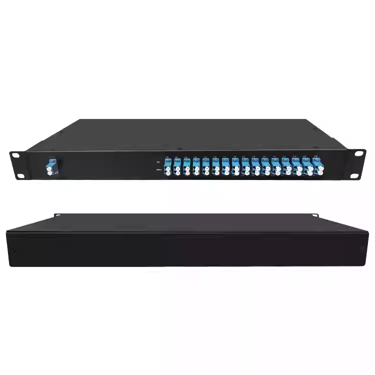
A rack port labeled “channel 21” does not tell the installer its direction, counterpart or accepted optical interval. Send your DWDM multiplexer supplier a frequency-to-port handoff that resolves those questions before assembly. Feiyi’s 1U rack DWDM module, LGX module and DWDM module cover different integration approaches. Begin with the required frequency grid, occupied channels and common-port route, then select the package and supplied connectors.
The buyer may be an equipment engineer preparing a rack, a contractor connecting the remote site or a distributor translating a network design into an order. All three need the same optical identities. The package can organize those identities, but it cannot resolve an incomplete frequency plan.
The DWDM multiplexer supplier needs frequency, spacing and direction in one record
Feiyi’s ordinary DWDM module families list ITU-grid channels and 100 or 200 GHz spacing. Their ordering notation includes 100G and 200G. In this context those entries identify channel spacing, not a guaranteed data rate of 100 or 200 Gbit/s. Keep the optical-grid request separate from the protocol and transmitter performance required by the completed link.
ITU-T G.694.1 is the reference for the dense frequency grid. Its technical text anchors the fixed-grid definition to 193.1 THz. A channel identifier should therefore be accompanied by its actual nominal frequency and the selected spacing. A shorthand channel number by itself can be misinterpreted when different conventions or grids are mixed.
The 100 GHz passband is not the space between channels
The ordinary module table gives a −0.5 dB channel passband of at least 0.22 nm for the 100 GHz option and at least 0.5 nm for 200 GHz. Spacing describes separation between nominal centers; passband describes the optical interval meeting a stated transmission condition. Do not approve a transmitter’s entire spectrum merely because its center lies on the selected grid.
An engineer should provide the required transmitter interval, including the conditions under which its center or spectrum changes. Compare that interval with the approved filter response for the supplied module. A channel-spacing value alone does not establish compatibility with every modulation format or laser-stability condition.
A rack handoff should trace one DWDM service across both assemblies
Take an intended service and identify its transmitter-side channel connection, local common route, shared fiber, remote common route and receiver-side channel connection. Repeat that tracing for each occupied wavelength. The installer should not have to infer the remote endpoint from the position of a connector on the local front panel.
- Assign the source frequency: use the nominal frequency and approved transmitter interval.
- Identify the local channel port: tie it to the supplied mux function and connector finish.
- Name the common connection: show the shared transmission route and its direction.
- Match the remote demux port: preserve the same optical identity through the receiving assembly.
- Attach the receiver condition: retain the loss and interference allowances applicable to that service.
This is a route description for the actual engineered link, not an assumed physical port order. A supplier can confirm the resulting assembly against it. If a panel label changes during mechanical design, update the route record before the installer receives it.
Mux-plus-demux ordering should identify the separate common routes
The ordering section distinguishes Mux, Demux and Mux+Demux. Confirm whether the supplied assembly contains the required functions for a fiber pair or another approved topology. A combined name should not be taken to mean that every service operates bidirectionally on one fiber. Draw the required transmit and receive paths explicitly.
For an engineering team handing the rack to a contractor, use site and direction labels that remain meaningful when the rack is viewed from the front. A left-to-right panel order is not a substitute for identifying the path. The contractor needs to distinguish common ports and wavelength ports before placing or moving patch connections.
A receiving engineer can compare the supplied frequency-to-port record with the rack drawing before connection. Mark unoccupied wavelengths distinctly from unassigned hardware positions. A reserve channel still has an optical identity even when no transceiver is attached. If the supplier changes the panel sequence for a packaging revision, preserve the frequency mapping and update the installer document together.
For two similar LGX modules, include enough identification to prevent swapping a mux at one endpoint with a demux intended for another route. The replacement’s mechanical fit does not establish that its optical function and channel subset match the removed unit. Confirm all three before treating it as an approved spare.
LGX, ABS and 1U DWDM packages should preserve the approved optical plan
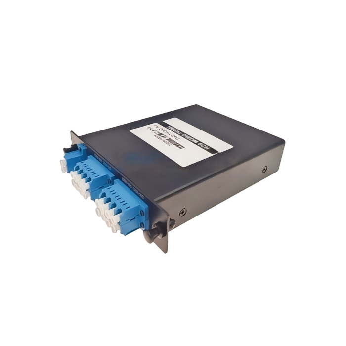
The LGX ordering option lists a 129 × 29 × 130 mm form and arrangements for insertion into two- or four-slot racks. The ABS choices include several envelopes, while the rack family provides a 19-inch 1U approach. Select a specific drawing rather than assume that every package option supports the same mounting or connector access.
An LGX replacement needs clearance at the connector end
Consider an integrator replacing a compact module in a populated slot. The module body’s nominal width may fit while its connectors or cable exits conflict with adjacent equipment. Check the selected connectors and the space required to disconnect them. Ask for the completed assembly drawing and retention arrangement, including any adapter or front-panel interface.
The cable options include 900 µm loose tube and 2 or 3 mm cable, with listed fiber lengths such as 0.5, 1 and 1.5 m. These options should be chosen for the actual endpoint distance and routing. A body dimension does not include every service loop or external termination needed in the rack.
The connector choices include LC, SC and FC in UPC and APC forms. Confirm the finish at each supplied interface and the matching connection on the installed equipment. Do not let a packaging change silently alter the approved termination. If the design moves from a pigtail ABS assembly to an adapter-facing panel, establish the changed test boundary as well.
DWDM channel loss should use the selected count and grade
The ordinary DWDM table lists loss no greater than 1.8 dB for four channels and 3.0 dB for eight channels. At sixteen channels, it distinguishes low-loss no greater than 3.5 dB and standard no greater than 5.0 dB. Record which selected limit applies to each supplied mux or demux; a sixteen-channel title does not identify the lower-loss grade.
A source and receiver connected through two devices need both applicable limits in the service calculation, along with all other installed route losses. Do not substitute a one-module reading for the whole path. If a unit is received with a different termination from the approved sample, confirm whether the previous result still represents the installed reference boundary.
Ripple and isolation cannot be collapsed into one DWDM acceptance number
The module family lists channel ripple no greater than 0.5 dB and adjacent/non-adjacent isolation of at least 30/40 dB. Ripple describes variation within the relevant channel response; isolation describes unwanted transfer from other channel conditions. An insertion-loss reading at the nominal center does not independently establish either property.
For a transmitter occupying a required spectral interval, ask for the applicable channel response across that interval. For an interference-sensitive receiver, identify the relevant adjacent and other occupied sources. A favorable low-loss result with only one transmitter active cannot automatically certify the complete populated-rack condition.
The family lists PDL no greater than 0.2 dB and wavelength-temperature shift no greater than 0.001 nm/°C. Those entries should remain attached to their specified conditions. A temperature coefficient is not itself an unlimited wavelength allowance: the transmitter interval, filter response and actual environment still need a combined assessment.
A three-port DWDM filter is an OEM routing component rather than a complete rack mux
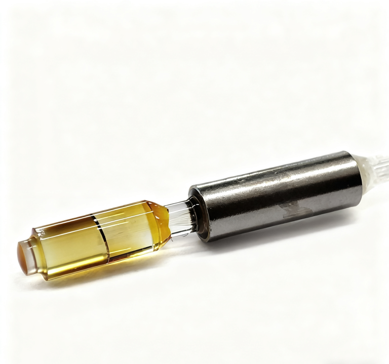
Feiyi’s three-port DWDM device separates a pass-channel route from a reflection-channel route. At 100 GHz it lists pass-channel loss no greater than 0.7 dB; at 200 GHz, no greater than 0.8 dB. The reflection-channel limit is 0.45 dB. These are route-specific entries, not one interchangeable loss figure for all ports.
The pass and reflection leads need a named wavelength route
An OEM integrating this device should identify which selected wavelength uses the pass route and which optical condition uses the reflection route. The device’s small package, listed as a 5.5 mm diameter by 35 mm cylinder, does not establish a complete multi-channel module. A chain built from multiple routing elements needs its own end-to-end allowance and path drawing.
The three-port product lists different passband conditions from the ordinary module: greater than 0.3 nm at 100 GHz and greater than 0.5 nm at 200 GHz under the named −0.5 dB condition. Use the selected device’s values rather than transferring the module’s 0.22 nm entry. Its listed operating range is also −20 to +70 °C, distinct from the ordinary module family’s −10 to +70 °C.
The DWDM OADM node requires route-specific approval beyond the terminal map
Feiyi’s DWDM OADM module addresses add/drop use. Specify the channels being added and dropped and those that must continue through the intermediate location. The product’s mux/demux-style table does not define every express-path loss or every possible direction of a proposed network.
A node installer should receive a drawing that keeps add, drop and continuing routes distinct. If the OADM is inserted into a working link, confirm the extra allowance on services that continue through it as well as the new local services. Obtain the selected node’s approved limits rather than borrowing a terminal-module figure for the continuing path.
For the ordinary module’s listed 300 mW power handling, identify the applicable aggregate common-port condition when multiple sources are combined. Source power on an individual channel does not automatically describe power at every downstream element. The selected assembly also needs approval for its actual environment; a component temperature entry does not establish cabinet certification.
The DWDM receiving file should reproduce the ordered paths
Request a per-channel identity record and measurements tied to the selected function, grade, connectors and reference wavelengths. The test should make it possible to match a measured route to a labeled panel connection. Preserve center-frequency and spectral acceptance requirements separately instead of reducing the record to one average loss across the assembly.
For shipment, require protection of the ordered panel or lead interfaces and identification that survives uncoiling and installation. Do not rely solely on the enclosure label when two similarly packaged units have different channel plans. Package them with the unit-specific mapping the contractor will use, without assuming a particular standard shipping procedure or fixed lead time.
Feiyi’s wavelength-multiplexing configuration discussion provides further context. Release the rack order when the supplier and installer can trace the same frequencies through the same named ports. If the next revision changes a channel, connector or route function, update that handoff before using the earlier acceptance record.