PM Optical Switch Manufacturer: Freeze the Optical Route and Electrical State Together
An engineer choosing a PM optical switch manufacturer has two designs to freeze at the same time: the optical route and the electrical state that selects that route. If those two descriptions live in separate documents, a switch can pass an optical inspection yet behave incorrectly when the controller is connected. Feiyi’s PM optical-switch range includes 1×2, 1×3/1×4, 2×2, and magneto-optic PM switch configurations, so the right starting point is the routing truth table rather than the connector list.
The published PM 1×2 Optical Switch provides a useful reference. It lists 1310±30 nm and 1550±30 nm wavelength ranges, typical insertion loss of 0.8 dB and maximum insertion loss of 1.0 dB, return loss of at least 50 dB, crosstalk of at least 55 dB, extinction ratio of at least 20 dB, and repeatability within ±0.02 dB. The same page includes latching and non-latching operation and 3 V or 5 V electrical options. Those optical and electrical facts should be approved together.
A PM optical switch manufacturer needs one truth table for light paths and control states
A 1×2 switch looks simple: one input routes to one of two outputs. In practice, purchasing needs to know what happens when each control line is energized, what state remains when power is removed, and how any status contacts report the selected path. Feiyi’s PM 1×2 page publishes pin behavior for latching and non-latching versions, making the control state part of the product definition rather than an afterthought.
Latching and non-latching PM switches belong in different controller designs
A latching switch retains its selected optical path after the drive signal is removed. A non-latching switch depends on the powered control state to hold or select its route. That difference affects firmware, power-failure behavior, and the way a system returns to service after a reset.
A buyer should therefore state whether the instrument requires the last path to remain after a control pulse or whether it requires a defined route while power is applied. That decision should appear on the electrical schematic and the purchasing record. Choosing the wrong actuation mode is not a minor substitution; it changes how the instrument behaves.
The controller voltage should be approved with the exact switch configuration
Feiyi’s PM 1×2 page lists both 3 V and 5 V options. Its electrical table gives 4.5–5.5 V for 5 V versions and 2.7–3.3 V for 3 V versions, with different current and coil-resistance values for latching and non-latching builds. The ordering information also identifies the selected voltage as part of the configuration.
For an OEM controller board, the correct switch cannot be defined only by wavelength and port count. The drive voltage and actuation type should be frozen before the harness and firmware are released. That prevents a later optical-equivalent substitution from creating an electrical mismatch.
PM optical switch manufacturer selection should begin with the route topology
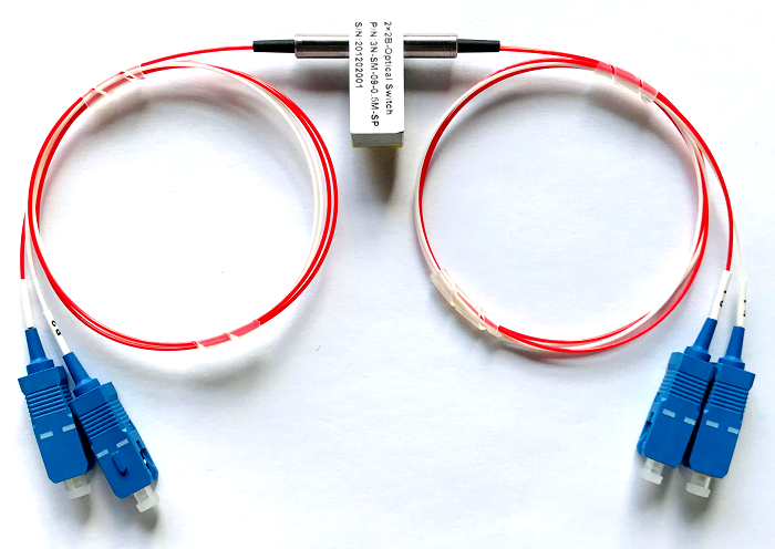
Feiyi’s PM switch family offers several topologies. A 1×2 device selects between two destinations. A 1×3 or 1×4 device supports a larger fan-out. A 2×2 device is used when two input/output paths need a different switching relationship. Magneto-optic PM switch products form another branch of the range. These topologies should be chosen from the instrument block diagram before electrical or connector details are finalized.
| Feiyi PM switch option | System question to answer first | What belongs on the controlled drawing |
|---|---|---|
| PM 1×2 Optical Switch | Does one source need two selectable destinations? | P1/P2/P3 route truth table, latching mode, voltage |
| PM 1×3 / 1×4 Optical Switch | Does the instrument need three or four selectable outputs? | Channel numbering, default state, control mapping |
| PM 2×2 Optical Switch | Are two optical paths being cross-connected or redirected? | Complete two-state port map and connector identity |
| PM 1×2 Magneto-Optic Switch | Does the project specifically require the magneto-optic product family? | Approved technology family, route, drive interface |
| PM 2×2 Magneto-Optic Switch | Does a 2×2 PM route need the magneto-optic version? | 2×2 route matrix and electrical interface |
A larger port count should not be purchased from channel count alone
Moving from 1×2 to 1×4 changes more than the number of fibers. The controller must identify four destinations, the cable harness must preserve channel identity, and service documentation must tell a technician which physical lead corresponds to each route. If the instrument only needs two positions, a larger switch can add unnecessary routing complexity.
For a distributor, the same principle applies to stock. “PM optical switch” is too broad for a shelf label. Port topology, wavelength family, latching behavior, and voltage should be visible in the SKU so visually similar packages do not become accidental substitutes.
Optical limits still matter after the electrical state is correct
Routing to the correct port is only the first acceptance condition. Feiyi’s PM 1×2 product page publishes typical insertion loss of 0.8 dB, maximum insertion loss of 1.0 dB, return loss of at least 50 dB, crosstalk of at least 55 dB, extinction ratio of at least 20 dB, PDL no more than 0.05 dB, wavelength-dependent loss no more than 0.25 dB, and temperature-dependent loss no more than 0.25 dB.
Crosstalk should be checked on the unselected path, not inferred from insertion loss
An optical switch can have acceptable loss on the selected route and still leak more power than expected into the unselected route. That is why crosstalk is a separate specification. In a measurement instrument or protection system, leakage to the “off” channel can create a false signal or interfere with another receiver even though the main output power looks normal.
Receiving inspection should therefore exercise each route, measure the selected-path loss, and verify the unwanted path under the same wavelength and launch conditions. The result can then be compared with the product-family limits used in the approved build.
Extinction ratio should be measured with the PM axis controlled through every switch state
A PM switch is valuable only if the surrounding PM chain preserves the intended polarization state. Feiyi lists an extinction ratio of at least 20 dB for the PM 1×2 model. The acceptance setup should use a known PM launch and consistent axis orientation through both selected paths.
If one route uses a different connector orientation or a stressed fiber lead, the measured result can change even when the internal switching mechanism is sound. Keeping the connector-key and PM-axis convention on the cable and switch documentation makes that difference easier to diagnose.
Switch time and life should be interpreted from the instrument duty cycle
Feiyi’s PM 1×2 page publishes switch time of no more than 8 ms and lifetime of at least 10^7 switching operations. Those numbers are more useful when connected to the system’s actual duty cycle. An automated test rack that changes paths thousands of times per shift places a different emphasis on cycling than a protection route that moves only during a fault or maintenance event.
A test platform should validate the route sequence the software will actually command
Feiyi lists network test systems among the applications for the PM switch. During prototype validation, the test sequence should exercise the same P1-to-output transitions that production software will use, including the timing between control commands and optical measurements. The objective is not to invent a new switching-speed claim but to confirm that the selected product family fits the instrument’s control rhythm.
For a manually serviced system, the emphasis may instead be on a predictable default or retained state after power loss. That again returns to the latching decision: the correct manufacturer configuration is the one whose electrical behavior matches the operating concept.
A PM optical switch manufacturer should see the failure-state requirement before production
Feiyi’s earlier article What a PM Optical Switch Supplier Must Know About Your Instrument’s Off State focuses on what the instrument should do when power is removed. A production handoff should turn that behavior into an explicit state table: powered route, de-energized route, status-sensor expectation, and any controller interlock.
The PM Photoswitch range provides the product-family view. The individual 1×2 page then gives the published electrical pin behavior and optical limits. Using both avoids a common mistake in which an engineer approves the optical device but a separate purchasing team selects the electrical variant.
Fiber and connector details should be added after the route and state table are stable
Feiyi’s PM switch ordering information includes fiber type, connector choice, fiber length, package, wavelength, switch type, and voltage. These fields are important, but they should sit underneath the already-approved optical/electrical behavior. If the controller expects a latching 5 V 1×2 unit, changing only a connector should not silently change the switching mechanism.
For repeat orders, keep the configuration code or complete ordered description with the customer part number. Port labels on the finished assembly should match the schematic, especially when several fiber leads emerge from a compact package.
Build the incoming test around the same controller boundary used in the instrument
A practical incoming test connects the switch to a defined 3 V or 5 V control source as appropriate, exercises every intended route, confirms any status-sensor outputs, and then measures optical transmission and leakage. The optical source should match the approved wavelength family, and the PM launch orientation should remain controlled while routes change.
Feiyi publishes a 27.0 × 12.6 × 8.0 mm size and 16 g weight for the PM 1×2 product, operating temperature from -20 to +75°C, storage from -40 to +85°C, and transmission power up to 500 mW. Those values help an OEM confirm enclosure and operating boundaries, but the project should not assume that every other PM switch topology uses the identical mechanical or electrical specification without checking its own product page.
Feiyi does not publish one universal packing method for all PM switch configurations. A buyer can still require the delivered part to preserve port identification, protect connectors or fiber leads, and keep the approved electrical variant traceable. Those are configuration controls rather than unsupported claims about factory packaging.
One additional procurement check is the relationship between the switch and any upstream PM patch cord. A controller revision can be electrically correct while a cable revision changes the keyed polarization interface. When a switch and patch cord are qualified as a pair, keep both part revisions in the instrument BOM. This is especially useful for field replacements: service personnel can replace one component without accidentally combining a new switch state table with an older cable-axis convention that was approved under a different assembly revision.
Release the PM switch only when optics, electronics, and port labels describe the same state
The final order should name the switch topology, wavelength, PM fiber and axis convention, connector or bare-fiber interface, latching or non-latching behavior, drive voltage, port-state truth table, status-sensor expectation where used, lead length, and the optical limits that will be verified. That is enough information for engineering, purchasing, receiving, and service teams to talk about the same component.
A PM optical switch manufacturer can supply several physically similar routing devices. The buyer’s job is to make the intended route and electrical state impossible to confuse. When one controlled document tells the technician where the light should go and tells the controller engineer how that state is selected, the switch becomes a repeatable instrument component rather than a box with multiple fibers.