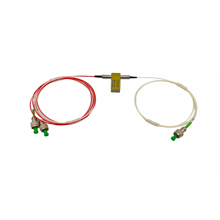
96 Channel 50GHz Athermal AWG Supplier: Control the Channel Map Before the Ribbon Fibers Reach the Rack
[Reading 53 lines from start (total: 53 lines, 0 remaining)]
96 Channel 50GHz Athermal AWG Supplier: Control the Channel Map Before the Ribbon Fibers Reach the Rack
A 96 channel 50GHz athermal AWG supplier is supplying more than a dense filter. Feiyi’s 96-CH 50G Athermal AWG combines 96 channels at 50 GHz spacing with a large fiber-identification and rack-integration task. The product page lists a clear-channel passband of ±6.25 GHz, wavelength stability of ±0.05 nm, 1 dB bandwidth of 0.2 nm, 3 dB bandwidth of 0.28 nm, optical insertion loss up to 1.2 dB in the displayed specification, adjacent isolation of 25 dB and non-adjacent isolation of 30 dB.
For an engineer or buyer, the first approval item should be the channel map and fiber map together. A 96-channel module can meet every optical filter value and still fail installation if a ribbon, label or LC port is mapped incorrectly. Feiyi’s page specifically lists SMF-28e, 900 µm common fiber, SMF-28e ribbons for channels, ribbon identification labels and LC/UPC connectors, making fiber management part of the product definition rather than an afterthought.
A 96 channel 50GHz athermal AWG supplier should deliver a channel-to-ribbon map before shipment
With 96 channels, a list of wavelengths is not enough. The rack team needs to know which channel is in which ribbon, which fiber color represents which position and how each ribbon is labeled at the end. Feiyi lists ribbon identification near endpoints and the conventional sequence of blue, orange, green, brown, grey, white, red, black, yellow, purple, pink and aqua for fiber identification.
The buyer should preserve that mapping in a controlled table that also shows the ITU frequency or wavelength. If the network lights only part of the 96 channels initially, keep the unused ports in the same map so future expansion does not change the naming convention.
Ribbon number and fiber color should never be the only way to identify a live wavelength
Colors repeat across ribbons. A technician should use the ribbon label, fiber position and optical channel identity together. This is especially important during emergency maintenance, when a visually familiar color can exist in several ribbon groups.
50GHz spacing demands a tighter wavelength handoff than a 100GHz shelf
At 50 GHz spacing, neighboring channel centers are closer together than in a 100 GHz system. Feiyi lists a clear passband of ±6.25 GHz on the 96-channel page. The network engineer should compare that useful central region with transceiver wavelength accuracy, drift and any additional wavelength-selective elements in the path.
If the design is migrating from Feiyi’s 40-CH 100G Athermal AWG, do not assume the same transmitter margin carries over. The denser grid should be reviewed as a new wavelength plan.
A 50GHz upgrade should be approved at the system level rather than as a port-count expansion
More channels in the same optical band can be attractive, but denser spacing changes the tolerance available to transmitters, cascaded filters and measurement equipment. Capacity and optical margin should be evaluated together.
The listed 1.2 dB insertion-loss value should be connected to the actual channel test definition
The Feiyi table shows optical insertion loss at the ITU grid with a maximum value of 1.2 dB. That is a strong number for a dense module, but the buyer should confirm whether the value applies across all 96 channels under the ordered profile and connector configuration. A high-density device should not be approved from one central channel measurement.
For a first article, capture loss across the channel set or the agreed sampling pattern. If later production uses a sampling plan, define which edge and center channels are included so the test continues to represent the full grid.
Adjacent isolation of 25 dB should be reviewed with fully loaded neighboring channels
Feiyi lists adjacent-channel isolation of 25 dB, non-adjacent isolation of 30 dB and total crosstalk of 20 dB. In a 96-channel system, neighboring carriers may be present on both sides of a channel. A receiver design should therefore use the isolation values in the context of the expected launch powers and channel loading.
Do not summarize the module as “high isolation” and discard the individual numbers. Dense DWDM troubleshooting depends on knowing whether interference comes from an immediate neighbor, a more distant carrier or the aggregate of many channels.
Wavelength stability of ±0.05 nm should be checked against the 50GHz passband and transmitter tolerance
The product page lists wavelength stability of ±0.05 nm. Because the grid is dense and the clear passband is ±6.25 GHz, the buyer should confirm how the supplier defines and tests wavelength stability for the ordered unit. The system budget should use one consistent frequency or wavelength framework rather than mixing tolerances without conversion.
Athermal operation means the module is designed to maintain channel behavior without active heater control. External AAWG documentation also describes passive operation without electrical temperature regulation, but the actual Feiyi temperature and stability values should remain the basis of the purchase file.
Temperature qualification should include edge channels as well as a convenient center channel
Feiyi lists operating temperature from -5 to 65 °C and operating humidity from 5 to 85% RH. If environmental performance is important, test or request data that represents the channel set rather than assuming one center wavelength proves the entire 96-channel grid.
PMD, chromatic dispersion and channel uniformity should stay visible in high-capacity system reviews
The page lists PMD values including 0.3 ps typical and 0.5 ps maximum in one row, another polarization-mode-dispersion line up to 1 ps, chromatic dispersion from -20 to +20 ps/nm, and insertion-loss uniformity of 0.8 dB typical and 1.3 dB maximum. Because the page contains overlapping PMD labels, a buyer who depends on these limits should request a current datasheet definition rather than combine the rows.
The useful procurement principle is clear: a 96-channel module should be qualified as a system component, not only by its low insertion loss. Uniformity, dispersion and polarization behavior can all matter as data rate and reach increase.
LC/UPC termination should be planned with the patch-panel architecture before ribbons are cut to length
Feiyi lists LC/UPC for the common interface and channel fibers on the current product page. It also specifies common-fiber length around 1000±50 mm and channel-ribbon lengths described in two segments around 500 mm. These dimensions should be checked against the actual shelf, splice tray or patch panel.
If the module sits deep inside a chassis, the factory pigtail length needs enough service loop without creating a dense coil of 96 channels. A rack drawing should show where the ribbon breaks out and where labels remain visible after installation.
A service technician should be able to trace one wavelength without separating every ribbon
Place labels where they remain readable after the module is installed. A mapping document is useful, but physical identification at the endpoints reduces the chance of disturbing unrelated live channels during maintenance.
The product page’s 17-port O-band table should not be used as the 96-channel C-band channel plan
The current Feiyi 96-channel product page contains a later section labeled as a 17-port AWG channel plan with O-band wavelengths around 1283–1297 nm. That content does not match the 96-channel 50 GHz C-band product described at the top of the same page. It should therefore not be copied into a procurement specification for this module.
For a 96-channel order, request the actual C-band channel plan associated with the ordered start channel and profile. Treating an unrelated table as the live port map would create exactly the kind of installation error that a high-density AWG project must avoid.
Package size should be checked with ribbon exit and connector service space
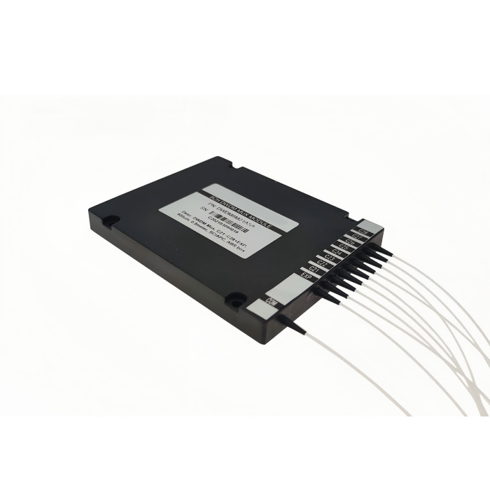
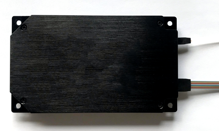
Feiyi lists dimensions of 120×70×10.5 mm. That compact body can fit inside dense optical equipment, but the ribbon and connector fan-out usually consumes more practical space than the metal package itself. Model the full service envelope, including bend radius and access to LC latches.
For OEM integration, define the module mounting datum and ribbon-exit direction before mechanical release. For a field-replaceable shelf, make sure a technician can unplug the intended channel without loading adjacent fibers.
Receiving inspection should sample both optical behavior and labeling integrity
A useful incoming plan for a 96-channel module begins with identity: 50 GHz spacing, 96 channels, ordered profile, connector configuration, common port and ribbon labels. Then verify wavelength alignment and loss according to the agreed channel sample or full-channel test. Finally, compare the physical labels with the channel map.
Labeling is not merely administrative on a 96-port optical product. A misidentified ribbon can produce a live-service incident even if the AWG chip itself is perfect.
A 96-channel service spare should preserve profile, start channel and fiber coding
A replacement described only as “96CH 50G AAWG” is incomplete. The spare should carry the same profile, channel range, common-port configuration, ribbon coding, connector polish and physical labeling scheme as the installed unit. If the network team changes any of those details, update the rack documentation at the same time.
This is especially important when several AAWG modules share one shelf. A mechanically interchangeable spare can still be operationally incompatible if its channel sequence or fiber presentation differs.
A repeat order should make the 96-channel map understandable without the original installation team
Once the first module is commissioned, retain the 50 GHz channel plan, start and end channels, clear passband definition, agreed insertion-loss and isolation values, wavelength-stability definition, temperature requirement, package, common-fiber length, ribbon lengths, LC/UPC terminations, ribbon numbering and fiber-color map. If Feiyi clarifies the overlapping PMD rows, attach that clarification to the controlled item.
Feiyi’s AWG module article discusses profile choice more broadly. This 96-channel article has a different purpose: preserving a dense optical and physical map so expansion and maintenance remain possible after the original engineering team has moved on.
Commissioning should test the channel map through the installed ribbon fan-out
After the 96-channel AAWG is mounted, do not stop at a bench acceptance report. Verify several channels through the actual common port, ribbon breakout and LC/UPC patching used in the rack. Choose representative channels near the low end, center and high end of the planned grid. This catches integration errors such as swapped ribbon labels, reversed numbering or an incorrect patch-panel assignment that would not appear in a factory insertion-loss result.
For a partially lit network, record which channels are intentionally unused. That prevents a later technician from treating a dark but reserved port as a fault and helps expansion work preserve the original frequency plan.
High-density maintenance should be planned before the first ribbon is dressed
Ninety-six channels create a serviceability problem as well as a capacity benefit. The rack layout should leave enough room to identify, clean and reconnect one channel without pulling neighboring fibers. If the module will be replaced as a complete unit, document the ribbon grouping and breakout sequence so a spare can be installed without rebuilding the fiber map from scratch.
This is also where the physical 120×70×10.5 mm module size can be misleading: the package is compact, but the service envelope of the ribbons and connectors is much larger. Treat that surrounding space as part of the deployment design.
[executed on device: SK-20260121JOTG (a251fff9-956e-47b5-9307-14fb53329ed2)]