An O Band Athermal AWG Supplier Needs an O Band Channel Plan
A familiar AWG housing can conceal an entirely different wavelength plan. An equipment engineer evaluating an O band athermal AWG supplier should begin with the optical channel map, rather than reuse the C-band drawing already approved for another rack. Feiyi’s 17-channel 150 GHz athermal AWG operates in the O band, with listed wavelengths from 1283.358 to 1296.680 nm. Confirm those channels against the transmitters and receiving interfaces before selecting the module, fiber exits or mounting arrangement.
This configuration is relevant to optical-system OEMs and integrators whose equipment requires the published O-band plan. It is not a smaller C-band AWG that can inherit the same amplifier, transceiver or labeling assumptions. Recover the whole wavelength route: source, AWG port, common fiber and matching device at the other end. The working channel map, rather than the shared case photograph, determines what the purchase must deliver.
Build the O band AWG channel map from the 17-port table
Feiyi lists 17 output fibers, one input fiber and 150 GHz channel spacing. Its channel plan identifies channel 1 at 233.6 THz and 1283.358 nm, and channel 17 at 231.2 THz and 1296.680 nm. These values establish the operating region. A channel-number label without its frequency or wavelength would leave an important part of the purchase undefined.
Port 1 at 233.6 THz is not a C-band numbering shortcut
Write the frequency and wavelength beside the physical port label. “Channel 1” does not automatically mean the first channel in a previously stocked DWDM system. In an O-band assembly, the number is meaningful within the selected plan. The source and receiver must use the corresponding optical value, rather than merely an apparently matching ordinal number.
An OEM using several AWG designs in one assembly area should keep the O-band mapping unmistakable. A technician can connect a fiber to the correctly numbered position while attaching a source from the wrong wavelength family. The error becomes harder to find if every stored module uses the same shortened name and the case exterior provides no useful distinction.
150 GHz spacing should not become a fixed nanometer interval
The table advances in frequency. Its wavelength entries do not form a perfectly constant numerical increment because frequency and wavelength are inversely related. Preserve the published mapping rather than constructing an approximate wavelength sequence from a pair of endpoints. Retain enough precision to identify the selected optical channel without changing the specification through rounding.
The ITU-T frequency-grid recommendation provides background for frequency-based WDM planning. Use the applicable approved product plan for this 150 GHz O-band device. A grid standard does not establish compatibility with an arbitrary source or another module’s channel allocation.
A channel schedule is more useful to purchasing than a verbal statement that the source is “near 1290 nm.” Include the required port, center frequency or wavelength and allowed source operating range. If a transmitter cannot identify its actual optical value, resolve that uncertainty before ordering the AWG around it. The supplier cannot infer the intended source from an enclosure drawing.
The O band athermal AWG passband has to admit the real source
The center wavelength starts the approval, but it does not define the complete transmission envelope. Feiyi’s table includes center-wavelength accuracy, insertion loss at center and over the full bandwidth, and several bandwidth definitions. These rows help an engineer separate nominal alignment from useful transmission when the source position or operating conditions change.
Center accuracy and 1 dB bandwidth answer different questions
The listing gives center-wavelength accuracy of ±0.05 nm, with 1 dB bandwidth of 0.23 nm and 3 dB bandwidth of 0.42 nm. Do not add these values indiscriminately into a larger acceptable source drift. Accuracy describes where the response is centered; a bandwidth definition describes transmission around that center under its stated loss condition.
A project team changing a transmitter after the AWG sample is approved should compare the new source with the admitted band. A source carrying the same nominal wavelength label can have different allowed operating behavior. Retaining the old AWG order while changing source approval can create a mismatch that the mechanical receiving check will not reveal.
For a multi-source equipment build, identify whether the approval concerns one representative source or every populated channel. A center-loss reading on one port does not establish the position and transmission response of the remaining ports. The sample report should identify which channels were measured and how the result supports the actual assembly being purchased.
Center loss and full-bandwidth loss remain separate order conditions
Feiyi lists typical center insertion loss of 2 dB and maximum of 2.5 dB. The full-bandwidth row lists 2.8 and 3 dB. Confirm the reference definition for the selected configuration and any connectors. A link budget evaluated only at the channel center should not be represented as covering every admitted source position.
This distinction matters when receiver margin is limited. Purchasing may choose the smallest quoted number while the engineer’s transmitter operates away from the exact center. Supply the required envelope and request evidence for the corresponding loss condition. Comparing an unlabeled maximum in one quotation with a typical center value in another creates a misleading supplier comparison.
The table also separates adjacent and non-adjacent isolation. Apply the appropriate condition to neighboring channels and other leakage paths. “High isolation” cannot replace identification of the interfering optical signals the receiver must tolerate. Keep the tested channel and interfering channels visible in the acceptance record instead of retaining only a single best result.

Why a 17-channel O-band module cannot inherit a 40-channel bill of materials
Feiyi also lists 40-channel 100 GHz, 48-channel 100 GHz and 96-channel 50 GHz AWGs. Count and spacing provide useful contrasts, but selection cannot be reduced to the number of fibers that fit inside an enclosure. Each option needs its own complete optical schedule.
| Catalog route | Change in the optical plan | Assumption that needs a fresh review |
|---|---|---|
| 17 channels, 150 GHz, O band | Published 1283.358–1296.680 nm schedule | C-band source and amplification choices |
| 40 or 48 channels, 100 GHz | Different count, spacing and product schedule | 17-port numbering and fiber identities |
| 96 channels, 50 GHz | Denser, higher-count arrangement | O-band source and passband approval |
In a distributor’s inventory, shared case appearance can encourage a single generic AWG label. Separate the optical plans before assigning shelf locations. Preserve operating band, channel count and spacing, followed by the approved port map and terminations. This record remains useful when the metal cases are visually indistinguishable.
For an engineer, changing from 17 to 40 channels is a system change rather than an item-count upgrade. Review the sources, receiving requirements, common port and other wavelength-processing equipment. A reusable mounting bracket does not establish optical compatibility. Establish the revised approval boundary before changing a purchase line to a higher channel count.
Review O-band compatibility throughout the rack
Feiyi’s rack-mounted EDFA describes C-band amplification. It does not provide a basis for amplifying the 1283–1297 nm AWG channels. Products belonging to one supplier’s range are not necessarily suitable for the same optical route; the selected operating ranges decide that relationship.
Keep the common fiber and amplifier boundary explicit
If the system drawing contains an amplifier symbol, identify its band and function before finalizing the AWG order. Purchasing can otherwise retain equipment from an earlier C-band design while changing only the wavelength-routing module. Such a rack may contain correctly delivered parts that cannot perform the intended combined optical function.
Apply the same review to monitoring equipment. Specify whether the receiver or analyzer used for approval covers the actual O-band wavelengths and whether measurement occurs per output or at the common port. A monitor configured for another optical region cannot establish acceptance merely because its connector mates with the lead.
An integration team should also identify which external connectors form the delivered measurement boundary. If the AWG is supplied with bare leads and the buyer terminates them, separate the module qualification from later connectorized measurements. If it arrives terminated, preserve that connector configuration with the source conditions and port mapping.
The 100 × 80 × 9 mm module needs a fiber-exit drawing
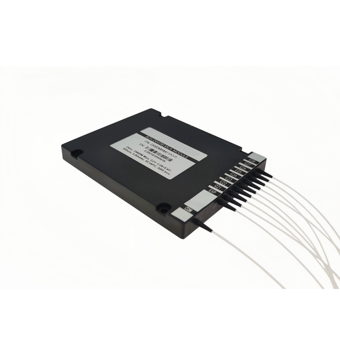
Feiyi lists a 100 × 80 × 9 mm module with 900 mm input fiber and 1,000 mm output fibers. Check exit directions and usable-length definitions against the enclosure. Seventeen terminated leads may demand more integration space than the metal body suggests, particularly when the panel and module are close together.
For an OEM mounting the AWG behind a front panel, decide where fiber identities remain visible after routing. A correct supplier map is insufficient if assembly removes labels or makes the leads indistinguishable. Preserve identification until the panel positions receive their final labels, and confirm that the supplier’s channel direction matches the panel numbering convention.
The table gives 25 dBm as the common-port optical-power handling entry. Confirm how this limit applies to the combined channel population and the delivered termination. A power description for the common port should not be silently copied onto every individual channel as a separate allowance. Include the intended simultaneous source population when assessing the optical loading.
During a supplier sample review, keep the common lead distinct from the seventeen channel leads in both the photograph and drawing. If the module is used in the reverse routing direction, confirm the corresponding port convention and test procedure. A consistent identifier is especially useful when the source and receiver are evaluated on different benches and each operator describes “input” from their own perspective.
Release the O band AWG order with spectral and mechanical evidence together
The approval file should identify the channel schedule, source conditions used to examine the passband and delivered mechanical configuration. Center-loss readings alone do not establish the admitted spectral envelope. A mechanical drawing alone does not establish which source belongs to each output. Keep these records connected by the actual approved part identifier.
Feiyi’s absolute-rating table describes −40 to +85°C under non-condensing conditions. Where the equipment requires transmission stability over temperature, define the optical checks and exposure conditions. Do not infer a completed qualification from a rating, or a heater requirement from generic table wording, without an approved product explanation for the ordered module.
During transport and receiving, protect the module and fiber exits while preserving channel identities through unpacking. State whether delivery includes bare leads or selected connectors. Agree documents and dispatch arrangements for the order; available catalog information does not establish universal stock, packing methods or lead-time guarantees.
The AWG passband-profile guide explains the wider response-shape decision. For this purchase, finish with the narrower O-band question: does the approved 17-channel plan admit the actual sources and reach the intended receiving interfaces? Freeze that answer with the drawing before ordering a case that merely resembles the AWG already in the rack.