850nm Multimode Optical Switch Supplier: Keep the Test Fiber and Switching Route Consistent
A single-mode patch lead is a poor shortcut for investigating an 850 nm multimode switch. Before a buyer rejects an incoming module, the launch and receiving fibers should match the intended channel. Feiyi’s 1×2 FSW OSW 850 nm is a starting point for equipment builders seeking an 850nm multimode optical switch supplier. Confirm the MM configuration, port direction, power supply and acceptance setup together; a connector that mates does not prove the correct optical path is being tested.
The module is relevant to optical routing, monitoring and protection arrangements using the published multimode configuration. A buyer replacing a source-selection path should recover the installed fiber and route first. A buyer building a new test instrument should establish the launch and detector arrangement before asking the supplier to reproduce a loss reading.
An 850nm multimode optical switch needs a multimode measurement boundary
Feiyi’s table separates FY-1×2-MM from FY-1×2-SM. The MM column gives a wavelength range of 850 ± 40 nm, while the SM column describes a different operating range and different return-loss and crosstalk entries. Do not evaluate the MM order against the most attractive values in the SM column.
Keep the 850 nm launch fiber consistent through the switch trial
Identify the fiber from the source to the module and from the module to the receiver. If the intended system uses a particular multimode core size, retain that configuration during sample comparison. A laboratory lead chosen only because its connector fits can change the collected power or the mode distribution that reaches the switch.
An OEM comparing incoming modules from two lots should hold the source and leads constant before interpreting a difference as a switch problem. The record should include the fiber type, wavelength and reference connections. A reading with an undocumented receiving lead is not strong evidence that the ordered MM configuration has changed.
Fluke Networks’ encircled-flux discussion explains why controlled launch conditions matter in multimode loss testing. Use that principle when defining a repeatable bench. It does not establish that a Feiyi switch has received a particular cable-test certification or that every equipment test should copy a cable-plant procedure.
MM return loss and crosstalk should use the corresponding column
The module table gives return loss and crosstalk of at least 30 dB for MM, compared with separate single-mode entries. State the quantity being measured and the intended reference port. An isolation result cannot be interpreted correctly without knowing the selected and unselected paths and the optical signal present at them.
A maintenance team can encounter an existing record that says only “switch loss passed.” Recover whether that result referred to one route, both routes or a complete equipment path. The buyer may need an additional trial before treating the historical record as an acceptance method for a replacement module.
Distinguish the 1×2 route from front-panel selection names
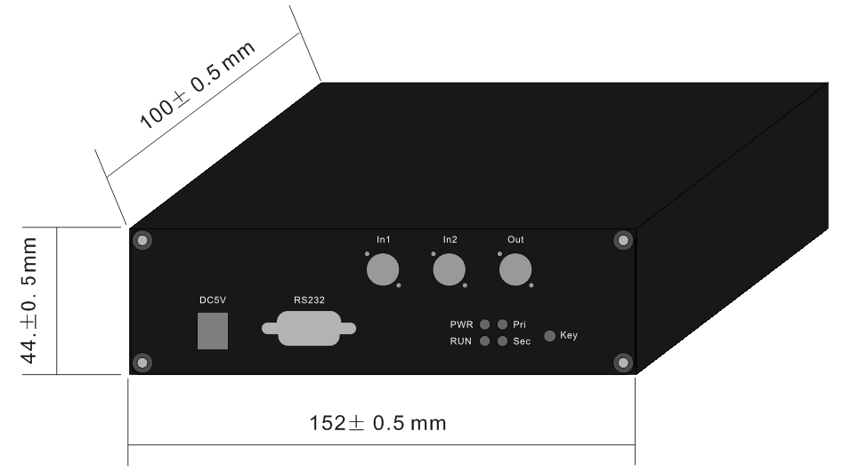
The product includes a routing illustration and control information. Obtain the approved map for the delivered configuration and relate it to the equipment’s source and detector connections. Names such as primary and secondary describe a control state in context; they do not alone establish the physical input/output direction of every configuration.

Confirm latching behavior for the actual 850 nm module
Feiyi offers latching and non-latching choices. Define the required optical state after removal of the drive or loss of operating power, and confirm it for the ordered unit. A stable selected route during normal operation does not answer the power-loss question that a protection or monitoring arrangement may depend on.
For a sensor builder switching between two observation paths, the acceptable unpowered state can be different from that of a network team preserving a preferred signal route. Write the required behavior as a port relationship rather than a vague statement that the switch should remain safe. Verify it during sample approval using the actual connected fibers.
3.0 V and 5.0 V options require the delivered supply interface
The optical table lists 3.0 or 5.0 V supply choices, while the module interface description refers to a DC5V connection. Confirm the selected configuration and connector before applying power. Do not infer that one delivered chassis accepts both supply choices from a family-level ordering entry.
If the module is integrated into equipment with an existing supply rail, give the supplier that requirement and obtain the approved electrical interface. A pinout, polarity or supply variation should not be discovered on the receiving bench by trial. The optical sample approval should retain the electrical configuration under which the routes were exercised.
Interpret 0.5 dB typical loss as a route-specific observation
Feiyi lists typical insertion loss of 0.5 dB and maximum of 0.8 dB for the corresponding table entries, together with repeatability no more than ±0.02 dB. Compare these values with the agreed path and reference setup. A reading containing unrelated leads, adapters and detector coupling is a different measurement boundary.
For each route, establish the source reference and the receiving connection before inserting the module. Keep the test configuration unchanged when changing state. If the receiving lead is unplugged and rebuilt between routes, investigate connection differences before assigning the observed change to the switch’s repeatability.
A repeatability trial should also distinguish repeated state selection from a single loss reading. Record the selected route and the conditions maintained during the trial. This is a proposed buyer method; it is not a statement that Feiyi has performed a particular number of switching cycles on the customer’s equipment.
The ≤8 ms switch entry does not include detector settling
The module lists switching time no more than 8 ms. Identify its applicable definition before using it in a sampling sequence. The receiving detector, communication response and acquisition software may introduce additional timing requirements. Measuring before the complete arrangement is ready can make one route appear unstable.
An optical test builder should establish a state-confirmation and measurement procedure using the delivered control information. The procedure should reject readings collected while the route is uncertain. An integrator replacing an installed module should compare this behavior with the existing controller rather than assuming a faster catalog value resolves every acquisition problem.
Compare the 850 nm module with the right neighboring products
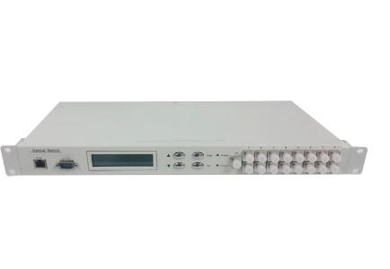
The FSW-1U-1X10-MM-FCPC rack instrument lists another 850 nm multimode configuration, but it addresses a broader instrument and channel-selection task. Consider it when the application needs the corresponding rack architecture, communication interfaces and multi-channel acquisition. It is not the same delivered object as a 1×2 module.
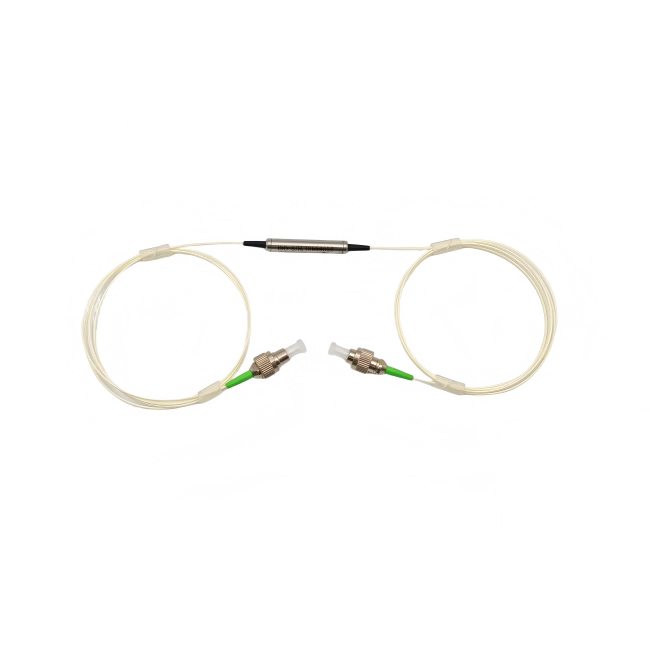
The 1×2 mechanical optical switch is relevant to a component-level routing design. Its approved optical and electrical arrangement should be compared separately. An OEM building its own controller may prefer that scope, while a maintenance team needs to preserve the actual module and control interface already installed.
The 1×2 magneto-optical switch is described with a 1520–1580 nm optical specification and a different drive discussion. The product does not provide a basis for direct substitution into this 850 nm MM path. A technology comparison must retain wavelength and fiber conditions, rather than selecting only the shortest advertised switching time.
Feiyi’s 1×8 route-and-drive guide explains how optical state and controller logic belong together. The narrower issue here is validating an 850 nm multimode branch. Keep the number of paths, optical fiber and module supply explicit when borrowing a review method from a different switch family.
Approve the MM module in its mounted cable arrangement
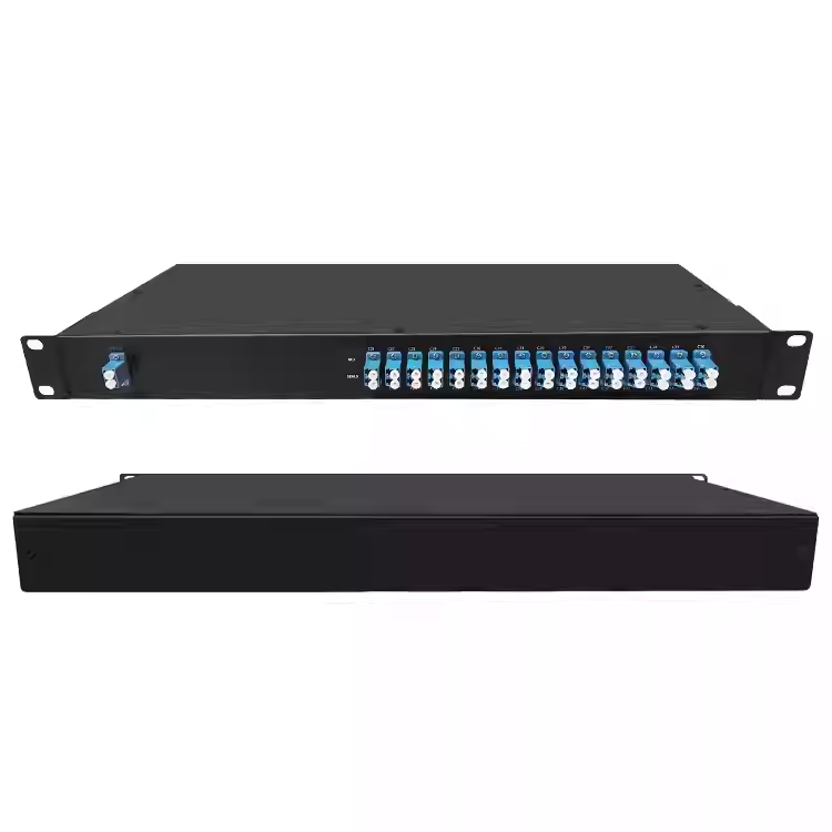
The supplied module should be compared with the actual available space and fiber exit route. Its illustration shows a housed instrument interface, not merely a loose optical tube. Check connector access and cable retention before treating the outline as proof that it fits an existing enclosure.
A maintenance buyer restoring a monitor may have two leads already labeled for the primary and alternate optical channels. Recover those labels and confirm their relationship to the approved module state. Reversing the physical association can make a controller display appear correct while the instrument observes the wrong source.
For an OEM, test the intended cable restraint with the sample. Compare the accepted optical reading before and after mounting, and distinguish loss introduced by the surrounding connections from the switch itself. If the routing requires an additional adapter or a different pigtail, include that change in the equipment qualification rather than hiding it inside a component acceptance number.
The 500 mW entry needs the actual source conditions
Feiyi lists transmission power no more than 500 mW. Check the intended source against that entry and obtain clarification for pulsed or otherwise unusual operating conditions. It is not an independently stated peak-power or pulse-energy specification. Preserve the approved source condition when exercising the selected and alternate routes.
The stated −20 to +75°C operating range should also be reviewed at the module location. A system enclosure can create a local condition different from ambient room temperature. The table does not establish qualification under every thermal cycle, humidity exposure or vibration requirement of an industrial instrument.
Consider a receiver test station that alternates between a reference source and a device under test. If those sources launch different mode distributions, the measured difference includes more than the optical switch. Keep a reference measurement for each source and branch with the intended receiver connection, then exercise the switch without changing those leads. This makes an unexpected reading easier to trace to a route, connection or source condition.
The measurement record should identify the selected state and when acquisition began after the switching command. Feiyi’s ≤8 ms entry describes the switch, while the source and receiver may have their own settling behavior. A controller that starts acquisition immediately after sending a command can create an apparent optical failure even when the selected path is correct. Establish the acquisition delay in the integrated test station rather than presenting the catalog switching time as a complete measurement-cycle specification.
Receiving records should identify the MM configuration before connection
Agree labeling that retains the ordered wavelength, fiber, supply and port mapping. If the order includes multiple module configurations, preserve those identities after unpacking. A receiving operator should not need to connect each unit to the production instrument to find out which configuration it is.
For shipping, specify protection for the module interfaces and its optical leads, together with the accessories required by the approved configuration. Confirm the documents and dispatch arrangement for the actual order. Neither a shared product photograph nor a broad application statement supplies evidence of available stock, a guaranteed delivery date or a particular export packing method.
Approve the purchase after the same 850 nm multimode test can identify both optical states with the intended leads and control supply. If the result changes when the launch or receiver fiber changes, resolve that boundary before changing the switch specification. A well-labeled MM configuration and a repeatable optical setup are more useful than a lower loss claim borrowed from the single-mode column.