3 Port CWDM Filter Supplier: Account for Each Pass and Reflection Stage
In a cascaded CWDM assembly, one channel may pass through several reflection stages before reaching its own transmission port. That route is the starting point when evaluating a 3 port CWDM filter supplier. Feiyi’s three-port CWDM device is relevant to OEMs building wavelength-routing assemblies and buyers selecting individual channel filters. First define the selected channel and the complete optical sequence; then compare port-specific loss, isolation and package choices against the intended assembly.
The individual filter should not be confused with a completed four-channel or eight-channel mux. It provides a configured transmission channel and a reflection path for other light. The buyer’s assembly determines how those paths connect and what the complete loss will be. This article follows that component-level decision, from the first channel drawing to the filter that arrives at the assembly bench.
Write a channel map for the three-port CWDM filter sequence
Feiyi lists channel wavelengths from 1270–1610 nm or 1271–1611 nm, with 20 nm channel spacing. State the intended center convention on the order and approved diagram. Those two family listings should not be silently merged into one exact center designation. The source, filter and surrounding assembly need a consistent configured channel record.
The 20 nm CWDM grid does not identify the selected port
The ordering information illustrates individual pass channels such as 1270, 1290 and 1310 nm. Confirm the selected transmission channel and the common/reflection labels for the delivered device. A range entry tells a buyer which family to examine; it does not identify the wavelength of a particular filter on the bench.
As general grid background, ITU-T G.694.2 defines a CWDM wavelength grid. Use the recommendation to clarify center designation where needed, while obtaining the actual selected center and passband from the configured product specification.
An OEM assembling several filters can put the transmission output of each selected channel on a separate connection and continue the remaining light through reflection. That possible route should be documented explicitly. The product’s three-port structure does not prescribe the buyer’s cascade order or prove that every proposed sequence has the same performance.
Common, transmission and reflection leads need persistent labels
Identify those three roles on the assembly drawing and receiving record. Do not use lead position or tube orientation as the only guide. A component can look similar after it is turned over, while the optical roles remain fixed. The person connecting the filter needs the configured map rather than a guess based on the photograph.
For a distributor supplying individual filters to several OEMs, preserve the channel and port definition with each configured stock line. A shared description such as “CWDM three-port device” cannot establish which unit belongs in a particular stage. A correct channel filter fitted into the wrong stage can create a routing fault without indicating a defective component.
Calculate CWDM cascade loss by counting the actual reflection stages
Feiyi lists pass-channel insertion loss no greater than 0.6 dB and reflection-channel loss no greater than 0.4 dB. Those are different route limits. For a channel that reflects through several upstream devices and then exits through transmission, count the reflection stages and its own transmission stage separately.
The following illustration uses only the listed component limits and assumes the approved route follows that sequence. It is a calculation example, not a measured assembly result. External terminations, splices, spectral conditions and other passive elements still need their own contributions.
| Illustrative channel route | Component-only limit calculation | Not included in this calculation |
|---|---|---|
| One transmission stage | 0.6 dB | External interfaces and other devices |
| One reflection, then transmission | 0.4 + 0.6 = 1.0 dB | Interstage connections and the rest of the link |
| Three reflections, then transmission | 3 × 0.4 + 0.6 = 1.8 dB | Assembly-specific loss beyond the listed stages |
A late-stage CWDM channel can have a different path budget
The example shows why one generic filter-loss line is insufficient for a cascade. Channels assigned to different stages may traverse different numbers of reflection paths. Review the loss available to each actual service rather than assuming that equal spacing means equal assembly loss.
An equipment designer changing the channel order should recalculate the affected routes. A change that reduces the stages traversed by one channel can increase those traversed by another. Preserve the routing drawing with the calculation so that the assembly team does not inadvertently reverse the intended sequence during layout.
A maintenance buyer replacing one stage should retain its configured channel and surrounding route. An individually acceptable filter with a different transmission channel does not preserve that stage. Confirm the replacement before disturbing the neighboring connections, and keep the original channel map available during the test.
Ask a 3 port CWDM filter supplier to define isolation in the correct direction
The Feiyi table lists pass-channel isolation at least 30 dB and reflection-channel isolation at least 13 dB. These entries should remain associated with their measurement paths and unwanted wavelengths. Do not advertise the higher number as a complete isolation guarantee between every pair of outputs in a cascaded assembly.
Obtain the relevant test direction and configured wavelength conditions for acceptance. A report should identify whether the result concerns unwanted light at the transmission output or the reflection path. The assembled cascade’s channel-to-channel behavior needs its own review rather than an unqualified copy of one component entry.
The table also lists directivity at least 50 dB and return loss at least 45 dB. These are separate quantities from channel isolation. A purchasing sheet that combines them into a single “isolation” value makes the requirement ambiguous. Keep the parameter names with their test conditions so that the supplier and receiving team check the same characteristic.
For an optical monitoring application, identify which light the receiving branch is supposed to carry and which bands it must reject. A filter’s selected transmission channel is a wavelength decision, not a power-ratio tap specification. If the intended monitor needs a defined fraction of broad-band light, reconsider whether the three-port channel filter is the appropriate optical function.
Use the ≥13 nm passband with the actual CWDM source conditions
Feiyi gives a channel passband of at least 13 nm at the −0.5 dB bandwidth condition. That condition belongs with the number. It is not the same as 20 nm channel spacing and should not be relabeled as the entire loss-free wavelength range. Obtain the configured spectral response needed to compare the filter with the intended source.
The table lists wavelength temperature shifting no greater than 0.002 nm/°C and an operating range of −10 to +70°C. The source wavelength behavior and component conditions still determine the complete passband review. A nominal center match is insufficient when the equipment requires behavior beyond the catalog conditions.
PDL is listed at no greater than 0.1 dB, with maximum handling power of 300 mW. Review the actual source power and polarization requirements against those entries. Low PDL is not evidence of a polarization-maintaining axis specification, and the power entry does not define arbitrary pulsed-source limits.
For sample approval, keep the configured center, optical direction and interface arrangement in the measurement record. A measurement at only one nominal wavelength answers a narrower question than a required spectral-range acceptance. Specify the acceptance scope before interpreting a supplier result as proof of the entire application.
Compare an individual CWDM filter with completed channel assemblies
The 4-channel CWDM mux/demux offers an assembled-channel route to examine when the buyer wants a complete component group rather than individual stages. Evaluate its approved channel map and assembly limits separately. The individual filter’s loss table is not the finished four-channel assembly specification.
The 8-channel CWDM mux/demux is another assembly scope. A buyer selecting it should verify the actual channels, connections and package. A larger channel count does not automatically meet an OEM’s desired cascade order or optical budget.
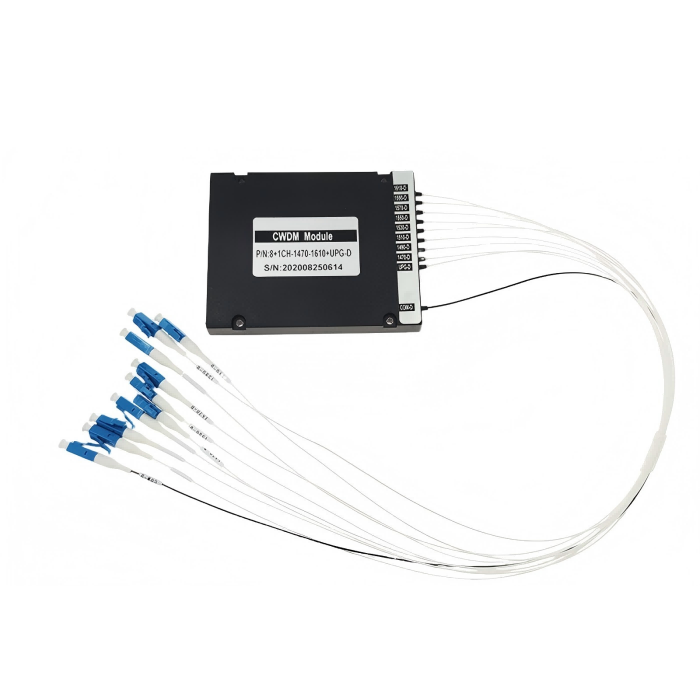
The CWDM OADM module belongs to a channel add/drop requirement. An individual filter may be part of a custom routing design, but that does not make every three-port order a completed OADM. Preserve the intended optical function and connection map when choosing between these products.
An OEM with a defined internal layout may prefer individual filters to control its own fiber routing. An equipment buyer seeking a completed channel assembly may instead need the mux or OADM scope. The decision should follow who owns the assembly design and which optical result needs to be supplied, rather than the smallest component photograph.
For a sample cascade, measure each selected route using the assembly order shown on the drawing. A comparison between the first and last selected outputs can reveal the effect of their different reflection counts, but it is still a result for that particular assembly and reference arrangement. Do not convert it into a universal loss promise for every number of channels.
If a selected route is unexpectedly lossy, retain its channel identity while examining the preceding reflection stages. A problem at an upstream connection can affect a later output without indicating failure of that output’s transmission filter. The stage map makes the investigation specific: it identifies which interfaces and reflection paths the affected light actually traverses.
For receiving evidence, keep the configured pass wavelength visible with both transmission and reflection results. The distinction between the 1270–1610 nm and 1271–1611 nm family listings should be resolved in the approved specification. A report using one center convention and a purchase description using another should be reconciled before assembly, rather than left for the technician to interpret.
When the package requires connectorized leads, document the external connection arrangement in addition to the component-stage calculation. Its loss and reflection behavior must be reviewed with the actual assembled route. The 0.6 dB pass and 0.4 dB reflection entries should not be turned into an unconditional guarantee for an enclosure containing additional interfaces.
Order the CWDM housing and leads for the stage being assembled
The three-port page lists Φ5.5 × 38 mm for 250 µm and 900 µm arrangements, and 90 × 20 × 10 mm for 2.0 mm and 3.0 mm options. Review the chosen outline with the planned sequence of filters and fiber restraint. Several small tubes can still need substantial routing space once their leads and connections are installed.
The ordering choices include bare fiber, 900 µm loose tube and larger cable options, with several fiber lengths and connector selections. Identify the selected termination and polish at each interface. The complete assembly budget should account for the actual connections; do not assume that a component-only calculation includes every delivered cord and adapter.
Agree labels that preserve the pass channel and port role after the filters are placed in the enclosure. Request shipment protection appropriate to the selected tubes or boxes and their fiber leads. Confirm the dispatch arrangement for the actual channel mix; the family range does not establish inventory, standard export packing or guaranteed lead time.
Feiyi’s CWDM mux/demux procurement discussion covers the wider assembly decision. For an individual-filter order, keep the configured stage and reflection count visible. Release the filters when the channel map, route-specific loss and delivered interfaces agree; an isolated low-loss number cannot approve the cascade.