What a PM Optical Switch Supplier Must Know About Your Instrument’s Off State
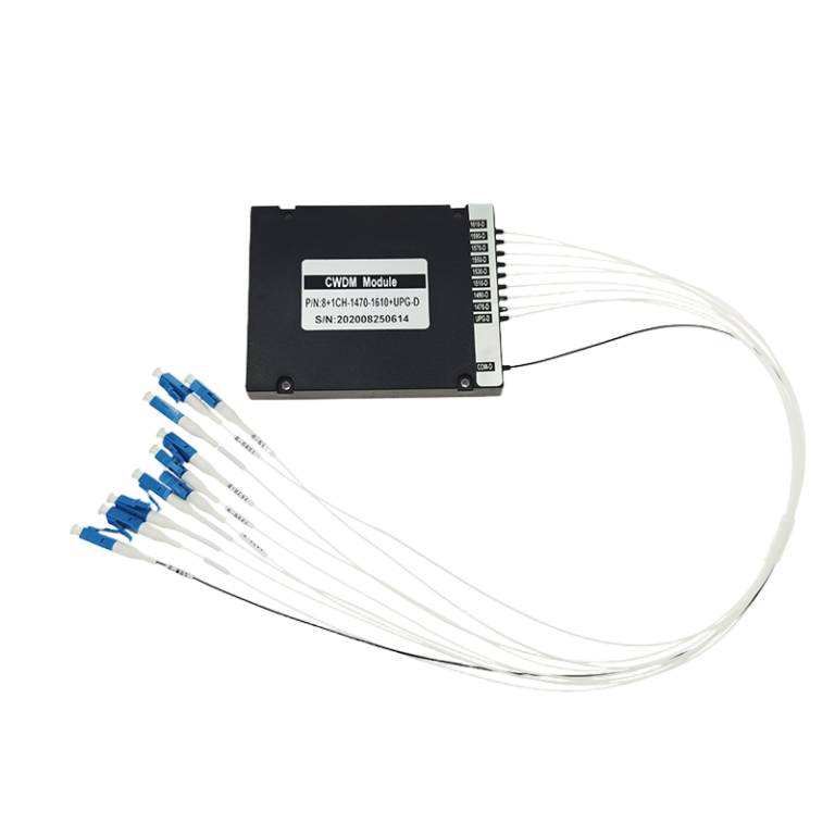
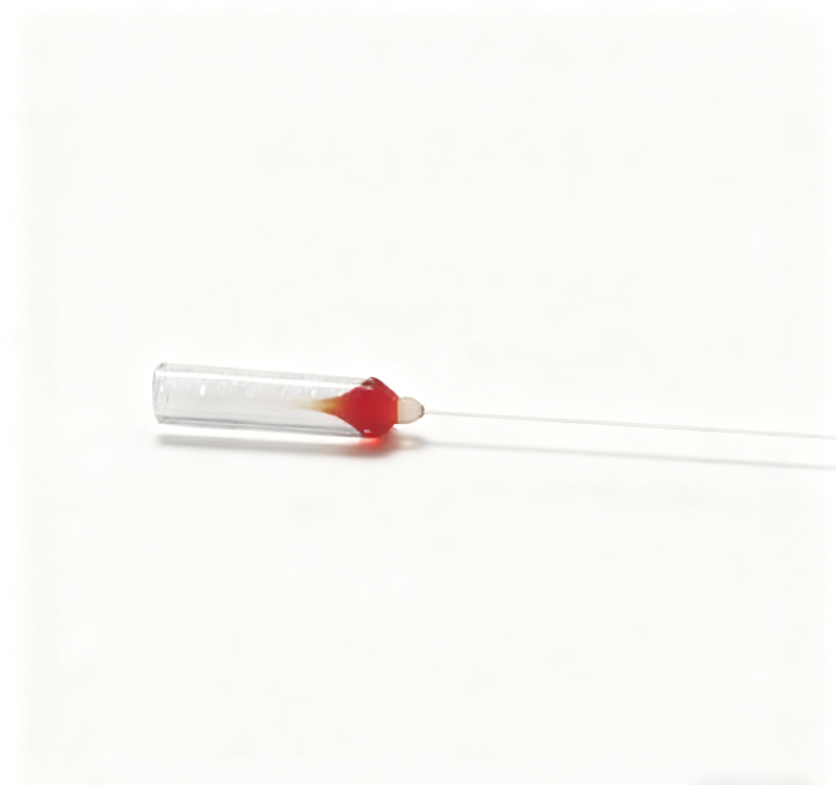
The instrument restarts, but its controller remembers yesterday’s channel while the optical switch is now somewhere else. That mismatch can corrupt a measurement even when the switch’s insertion loss is excellent. An OEM evaluating a PM optical switch supplier should define the optical route after power loss, the action that selects a channel and the condition that permits acquisition to begin. Feiyi’s PM 1×2 switch provides a starting point for two-route selection; its PM 1×3/1×4 family addresses more destinations. Approve their control behavior together with the PM fiber interface before releasing the controller board.
Ask the PM optical switch supplier what happens when drive power disappears
Latching and non-latching choices describe materially different control arrangements. A latching selection retains its selected state after the drive action is removed, while a non-latching arrangement has a defined unpowered behavior that must be confirmed for the selected build. The purchase specification must distinguish loss of the drive signal from loss of the instrument’s other supplies. Neither label alone establishes that the whole system reaches a safe or measurement-ready condition.
A latching PM 1×2 switch still needs an instrument startup sequence
Feiyi’s PM 1×2 listing offers latching and non-latching options and identifies 3 V or 5 V drive choices. Those are orderable control details. If the design uses a latching device, the firmware should not assume its own stored channel value proves the current optical route. Establish how the system commands or verifies its startup state before taking the first measurement.
For a two-channel test fixture, one route may lead to a reference and the other to the device under test. Restarting in the wrong route can produce a plausible reading associated with the wrong item. Describe the reference and test destinations on the circuit and optical drawings, then make the initial channel-selection action part of the instrument’s initialization. The requirement is route identity, not simply “switch powers on.”
Sercalo’s official switch-family overview distinguishes momentary and latching configurations. It is useful background for this control choice, but does not establish the default route or wiring of a Feiyi device. Obtain the approved Feiyi electrical diagram for the exact voltage and switch type ordered.
The PM 2×2 switch requires a complete connection state, not one channel name
Feiyi’s PM 2×2 optical switch is a different routing arrangement from a single input selecting one of two outputs. Its approval must identify the intended port connections in each state. A controller field named “channel 1” is inadequate if it leaves the second optical route undefined. Keep both connections in the accepted optical diagram.
The listing includes a 27.0 ×12.6 ×8.0 mm housing, 3 V or 5 V supply options and an extinction-ratio entry of at least 18 dB. Record the selected construction rather than assuming the PM 1×2 board footprint, drive arrangement and polarization allowance transfer unchanged. Similar package dimensions do not prove that the optical state map or electrical pin assignment is interchangeable.
Separate PM switch transition time from the moment acquisition becomes valid
The PM 1×2 and PM 2×2 tables list switching time no greater than 8 ms. The PM 1×3/1×4 family lists 10 ms. These values help compare component choices, but the instrument cycle may also include command transmission, electrical drive, optical settling and detector integration. A controller should not start collecting accepted data merely because it has issued the channel command.
Luna’s guidance for automated switch-based measurements emphasizes avoiding acquisition during a switch transition. Apply that sequencing principle to the equipment’s own detector and controller. The article’s instrument commands are specific to Luna equipment and should not be copied into a Feiyi component driver.
- Stop or finish the present acquisition. Retain the channel identity associated with its data.
- Select the requested optical route. Apply the approved electrical drive and any available state verification.
- Allow the accepted settling interval. Base it on the complete instrument test, not only the catalog switch-time entry.
- Acquire and label the next measurement. Associate the result with the confirmed route.
The 1550 nm PM magneto-optic switch addresses a different timing requirement
Feiyi’s PM 1×2 magneto-optic switch lists a test wavelength of 1550 nm, a 1525–1565 nm range and switching time no greater than 100 µs. Its ordering information identifies PM1550 fiber and 5 V operation. It is therefore a distinct candidate when a 1550 nm instrument needs a faster component transition than the millisecond-switch options provide.
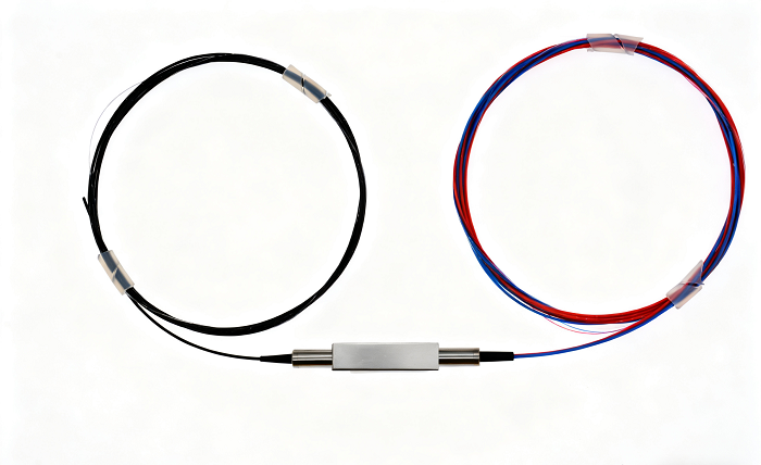
A faster component is not automatically the right replacement. Its wavelength range, insertion loss, extinction ratio, required pulse and controller behavior must fit the instrument. The listing’s pulse-duration entry of at least 200 µs concerns the drive requirement; it should not be confused with the listed optical switching time. Keep the two values in different fields of the board-approval record.
Agiltron’s description of solid-state PM optical switching explains the general relationship between an electrical selection and retained optical routing. This supports understanding the mechanism. Its speed, lifetime, integrated functions and qualification claims belong to its own products and are not Feiyi specifications.
Qualify every PM switch route under the same polarization launch
For a sensing instrument that expands from two outputs to four, adding ports changes the acceptance task. Each selected route must preserve the required optical throughput and polarization condition. A good result on the first output should not approve three unmeasured outputs, especially when the instrument compares small differences between sensing channels.
The PM 1×3/1×4 family has wavelength-dependent loss and extinction-ratio entries
The Feiyi PM 1×3/1×4 table lists a typical insertion loss of 0.8 dB and maximum of 1.0 dB for the 1310/1550 nm choices. Its 780/850/980/1060 nm choices have different listed values: typical 1.3 dB and maximum 1.8 dB. The respective extinction-ratio entries are at least 18 dB and at least 16 dB. Do not approve a shorter-wavelength variant using a telecom-band acceptance limit without an agreed device specification.
The same listing states that its principal specifications exclude connectors and gives separate connector-related adjustments. That makes the termination boundary important. Decide whether the acceptance result describes the component with bare fiber, the delivered connectorized component or the installed instrument path. A connectorized test should not be compared to a bare-device figure as if the extra interfaces did not exist.
The PM 1×2 table lists an extinction ratio of at least 20 dB. That is a different entry from the PM 2×2 value and the shorter-wavelength multiport values. Keep the relevant product requirement in the acceptance sheet. A generic order instruction saying “all PM switches meet 20 dB” would overstate what these different listings show.
PM1550 test jumpers must keep their axis reference unchanged between outputs
A Feiyi PM 1550 nm patch cord is a relevant connection option for a 1550 nm PM switch test. Specify its connector and axis orientation consistently with the device under test. If the output lead or adapter is changed between channels, preserve the reference arrangement and inspect the connection before attributing a changed reading to the switch.
Insertion loss, extinction ratio and unselected-channel leakage answer different questions. The first concerns throughput on the selected path; the second concerns polarization separation; the third concerns light reaching an unintended route. Record them separately. A low selected-path loss does not demonstrate that an unselected detector receives sufficiently little light, nor that the selected signal retains the required polarization.
Luna’s optical-switch datasheet illustrates why repeatability, crosstalk and insertion loss are specified as distinct measurements. Use that distinction to design the acceptance record. Its numerical values and test-cycle conditions should not be assigned to the Feiyi switch; agree the conditions for the actual part.
Approve the PM switch drive board together with its optical leads
The PM 1×2 and PM 2×2 listings show different drive-current and resistance entries for latching and non-latching configurations at 3 V and 5 V. The controller designer needs the selected variant’s electrical data rather than one approximate current value for the whole family. Identify the voltage tolerance, permitted drive pattern and pin function in the board file before the first powered connection.
The PM 1×3/1×4 page includes state-sensor and relay-control information. Ask the supplier to confirm the applicable drawing for the actual port count and switch type. Avoid relying on a copied pin table whose variant is unclear. A state indication is useful only when firmware interprets it according to the correct electrical definition; it should not be treated as direct proof of every optical performance requirement.
Lead handling also belongs to the board design. A compact component mounted beside a connector or enclosure wall may need more space for a relaxed fiber exit than the housing dimensions suggest. Agree the lead construction and lengths, reserve routing room and keep the fiber from being clamped by the cover. Specify connector protection and identified leads for delivery without assuming an undocumented standard packing method.
For mixed production of 1310 nm and 1550 nm instruments, keep wavelength, PM fiber, supply voltage and latching choice visible on receiving labels and internal part records. The housing and connector shape can look similar across variants. A controller that operates electrically with the wrong component can conceal an optical mismatch until the final test.
The existing Feiyi comparison of PM switch technologies is useful when the component mechanism is still undecided. For board release, narrow that broader comparison to one accepted route map, one drive configuration and the actual timing and polarization conditions of the instrument.
Test the PM instrument’s restart before treating a channel command as a measurement
Run the agreed acceptance sequence through a deliberate power interruption and restart, with the source and detector managed according to their own operating instructions. Verify which route the controller establishes, whether it identifies that route correctly and when the first accepted reading is acquired. Include transitions between the actual reference and measurement destinations, not only repeated operation of one output.
If the instrument needs a retained route through loss of drive, select and verify that behavior explicitly. If it needs a defined return state, resolve the non-latching behavior and startup action. If it needs faster 1550 nm selection, compare the PM magneto-optic option with its own loss, extinction-ratio and pulse requirements. These decisions should be made from the instrument’s required operating state, then written into the component and board approval together.
Release the order when the electrical engineer, optical engineer and purchaser can all identify the same startup route and the same point at which data becomes valid. An unexplained off state should remain an open design issue, even when the switch meets a favorable loss figure. The component is useful only when the instrument knows where its light is going.