PM In-Line Polarizer Manufacturer: Specify Polarization Purity, Power and Axis Together
A buyer looking for a PM in-line polarizer manufacturer is usually trying to clean up or define the polarization state inside a fiber system without moving into a free-space polarizer assembly. The first decision is not connector type. It is whether the system actually needs polarization filtering, what wavelength and optical power reach the device, and whether the surrounding PM fiber is launched on the intended axis.
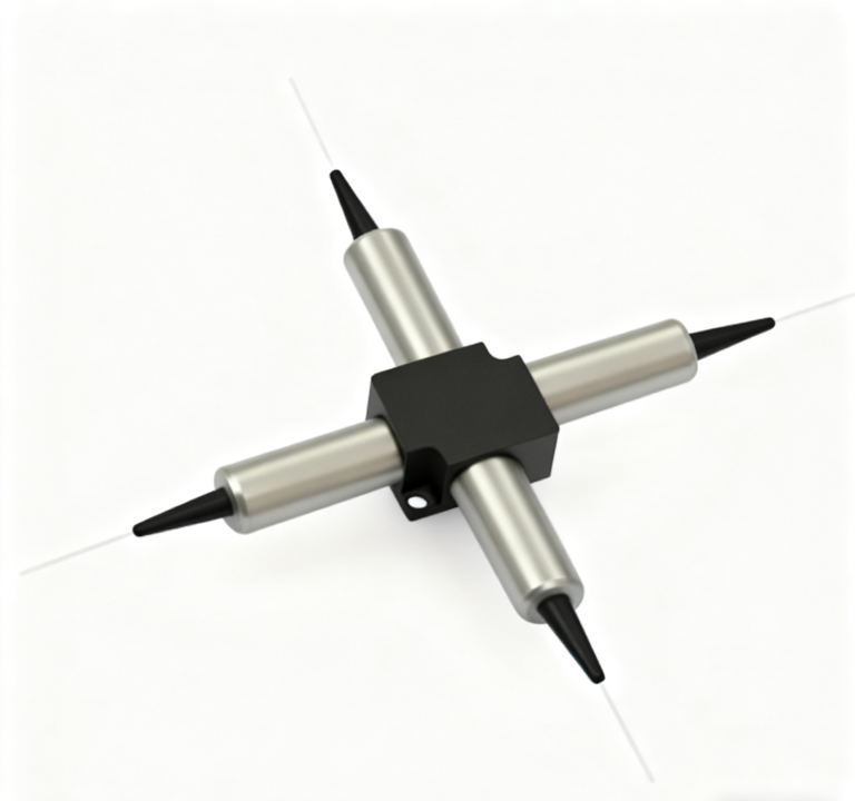
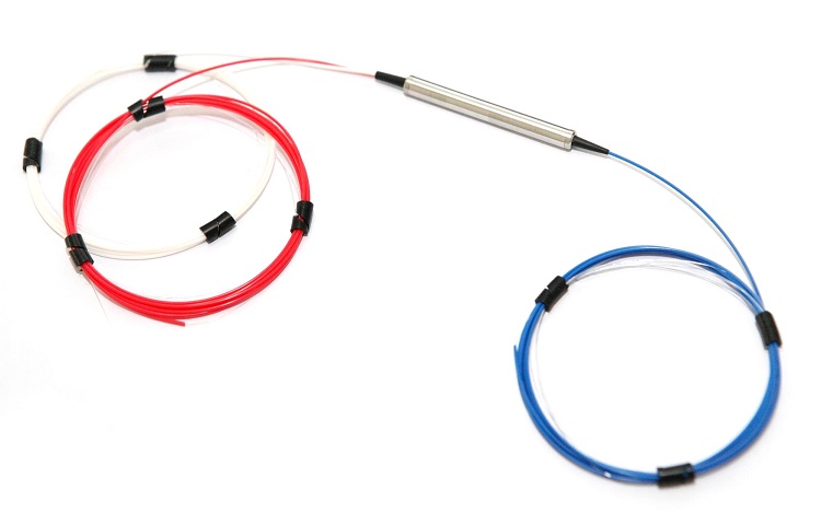
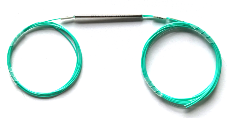
Feiyi publishes PM in-line polarizers at 780, 850, 980, 1064, 1310, 1550 and 2000 nm. Its 1550 nm product page gives enough detail to show how the family should be specified: operating wavelength, insertion loss, extinction ratio, fiber type, working axis, power and temperature range all belong in the engineering file.
A PM in-line polarizer manufacturer should first confirm why the system needs polarization cleanup
An in-line polarizer passes one polarization orientation while strongly suppressing the orthogonal component. That makes it useful when a laser, amplifier, sensor or test setup needs a cleaner linear polarization state. It is not a general-purpose optical attenuator and it is not a substitute for an isolator.
Use an in-line polarizer when polarization purity is the problem
Feiyi’s PM 1550 nm in-line polarizer is published for 1550 nm operation with a +/-50 nm operating range. Typical insertion loss is 0.3 dB and maximum insertion loss is 0.5 dB. The page lists typical extinction ratio of 30 dB and a minimum extinction ratio of 28 dB at 23 deg C for the PM fiber type.
Those figures make the device relevant where an optical chain has accumulated unwanted orthogonal polarization content. For example, a coherent test setup may require a well-defined linear state before light enters a polarization-sensitive component. In that case, the polarizer solves a specific problem that a standard PM patch cord alone may not solve if the incoming state is already impure.

Do not use a PM polarizer to solve a back-reflection problem
A laser that becomes unstable because reflected light returns toward the source needs an isolator function. Feiyi’s PM isolator family is designed around reverse-light isolation, with single- and dual-stage versions at key wavelengths. An in-line polarizer may improve polarization purity, but it does not replace the directional protection of an isolator.
Likewise, if the problem is excessive detector power, a PM VOA is the relevant family. Feiyi publishes PM VOAs from 780 through 2000 nm. A VOA changes optical level; a polarizer changes the polarization content. Putting both under the vague label “loss device” would hide the reason each part exists.
PM in-line polarizer manufacturer selection should include power, not just extinction ratio
Feiyi’s 1550 nm ordering information lists average-power options of 0.3 W, 1 W, 2 W, 5 W and 10 W. That range shows why power belongs early in the RFQ. Two systems can use the same 1550 nm wavelength and require very different polarizer configurations because one is a laboratory source and the other sits in a higher-power fiber laser path.
Measure power at the polarizer location rather than at the laser nameplate
If an amplifier, coupler or combiner sits before the polarizer, the optical power at that point may differ from the source output. The engineer should specify the expected power at the device, including operating margin required by the project. This prevents the manufacturer from receiving a nominal source number that does not describe the component’s real load.
For a low-power test setup, insertion loss and extinction ratio may dominate the design review. For a higher-power assembly, the first screening question is whether the ordered power configuration matches the actual path. Both systems can still use the same wavelength and PM fiber family.
Power capability does not remove the need for connector and fiber definitions
The 1550 nm page lists SM-28E or PM1550 as input/output fiber choices and slow-axis operation with fast-axis cutoff. It also shows connector options such as FC/PC, FC/APC, SC/PC and SC/APC, with fiber-length choices. Those details remain important at every power level.
A high-power capable part connected through the wrong PM axis or incompatible connector still fails the system requirement. The purchase description should therefore put wavelength, power, fiber, axis, connector and lead length in the same controlled configuration.
The PM 1550 nm in-line polarizer gives buyers a concrete acceptance baseline
In addition to the loss and extinction-ratio values, Feiyi publishes return loss of 50 dB, minimum fiber length of 1 m at each end, an operating temperature range from -10 to +75 deg C and storage from -40 to +85 deg C. Package dimensions are listed in cylindrical formats around 5.5 mm diameter.
Extinction-ratio testing needs a defined PM launch condition
A polarizer cannot be meaningfully accepted with an uncontrolled launch. The test setup should define the wavelength, input polarization orientation and how the PM fiber is held. Sharp bends, twisting or uncertain connector key orientation can change the measured polarization state and make results difficult to reproduce.
For incoming inspection, record the source and measurement method used for the approved sample. If the project uses connectorized PM patch cords on both sides, confirm that their key orientation matches the polarizer’s working-axis convention before treating a low extinction-ratio result as a component defect.
Insertion-loss measurement should follow connector cleaning and end-face inspection
A 0.3 or 0.5 dB specification is small enough that dirty connectors can distort the result. Connectorized samples should be inspected and cleaned before measurement. Bare-fiber variants require a consistent splice or launch method. The goal is to measure the device rather than contamination or a poor temporary connection.
These are practical reasons to keep the approved test method with the product record. A repeat order is easier to compare when both buyer and manufacturer know how the first sample was measured.
Wavelength families should be approved independently even when the product name is the same
Feiyi’s PM in-line polarizer range covers 780, 850, 980, 1064, 1310, 1550 and 2000 nm. That broad coverage supports several optical platforms, but it does not make the components interchangeable. Fiber type, source technology, power and surrounding components can change substantially between 780 nm and 2000 nm.
980 and 1064 nm laser systems should use their own PM fiber and test source
A 1064 nm polarizer belongs in a laser chain built and measured at that wavelength. Copying a 1550 nm acceptance setup can produce irrelevant data. The engineering file should name the source wavelength, PM fiber family and any power requirement specific to the 1064 nm path.
The same is true at 980 nm, where the system may sit around pumping, amplification or sensing functions. A manufacturer with several wavelength products is useful because the procurement process can remain consistent while the actual optical specification changes.
2000 nm designs deserve a separate material and detector review
At 2000 nm, the surrounding source, fiber and detector environment differs from conventional 1310/1550 nm telecom hardware. Buyers should therefore treat the 2000 nm in-line polarizer as its own qualified part and confirm the applicable published data for that model. A family label is not a substitute for wavelength-specific approval.
Prototype approval and repeat production need the same polarization reference
A prototype polarizer is often tested by the engineer who designed the optical setup. A repeat lot may be received months later by a quality technician who was not involved in the original alignment. If the product record contains only the wavelength and connector, the second team may not reproduce the launch condition used to approve the sample.
Freeze the accepted axis, connector and measurement method with the sample record
The approved configuration should state the PM fiber type, the working-axis convention, connector polish, lead length and the extinction-ratio test arrangement. If a specific source, polarizer controller or analyzer orientation was used, the internal acceptance procedure should identify it. This does not require turning the purchasing file into a laboratory manual, but it should contain enough detail for another technician to obtain comparable results.
For connectorized parts, include how the connector key corresponds to the PM axis. For bare-fiber products, note the launch or splice orientation. If the device is used at a higher power option, preserve the exact ordered power configuration as well. That keeps a later reorder from being reduced to “same 1550 nm polarizer as before.”
Packaging instructions should protect the surfaces that affect the acceptance test
The public Feiyi pages specify optical and ordering data but do not state one universal packing method for every in-line polarizer configuration. Buyers should therefore agree the protection required for the actual part. Connector end faces need caps and contamination control, while bare-fiber leads need bend protection and clear identification. If several similar wavelength variants are delivered together, the inner package label should make the wavelength and product code obvious before the bag is opened.
That packaging detail has a direct technical purpose. A contaminated connector can increase apparent insertion loss, and a damaged or tightly bent PM lead can complicate polarization measurements. Protecting the interface makes incoming data more representative of the component that was manufactured.
Where a PM polarizer belongs in a larger Feiyi component chain
A typical polarization-sensitive chain may include a PM patch cord at the removable interface, a PM 1550 nm in-line polarizer to clean the state, a PM circulator for directional routing and a PM VOA where controlled attenuation is required. Each part has a separate reason to exist.
Feiyi’s PM in-line polarizer range is the right starting point when the central problem is polarization purity. The PM isolator laser-chain guide is more relevant when reverse light is the risk, while the PM VOA article addresses excess optical power.
The purchase description should state the polarization problem in one sentence
Before sending an RFQ, write one sentence explaining what the polarizer must do: for example, “clean the 1550 nm PM path before a polarization-sensitive receiver while handling the specified optical power.” Then add the measurable configuration鈥攚avelength range, insertion loss, extinction ratio, power, fiber, working axis, connector and lead length.
That approach gives a PM in-line polarizer manufacturer enough information to match the correct family and gives incoming inspection a clear reason for every test. It also prevents the polarizer from being substituted for an isolator or attenuator simply because all three are small fiber-coupled devices.