Ask an FBT Splitter Supplier to Separate the Tap Ratio From the Wavelength Window
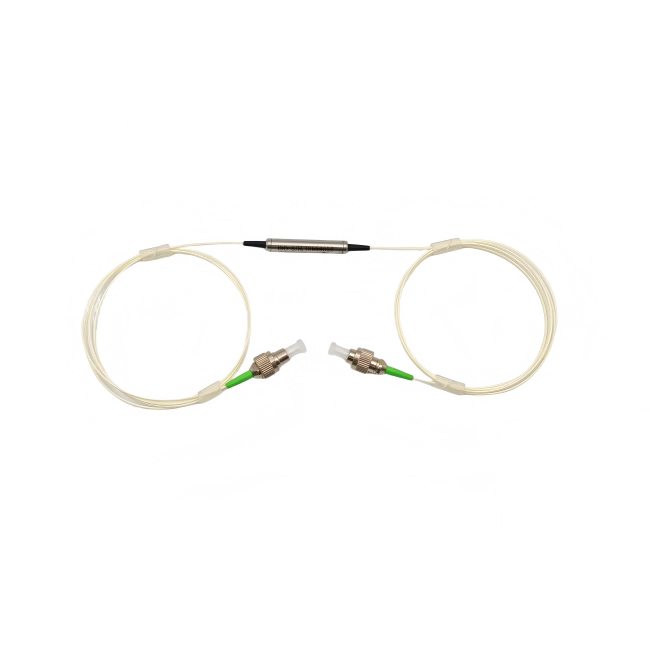
“Ten percent for monitoring” describes a power division, not a wavelength specification. A tap that suits a 1550 nm measurement may still need separate approval when the same line carries 1310 nm light. Ask an FBT splitter supplier to confirm both the branch ratio and the operating windows. Feiyi’s single-mode fused coupler and dual-window coupler are relevant for ordinary SM monitoring routes. Identify the through lead, monitor lead and actual wavelengths before interpreting a paired loss figure.
This approach suits network monitoring, optical sensor assemblies and distributors supplying tap components. It also helps a maintenance buyer preserve a known route without accidentally replacing a dual-window part with a single-wavelength selection. A ratio written on an item label should never be the only identification used for that replacement.
An FBT splitter supplier should keep ratio and wavelength as separate order fields
Feiyi’s single-mode coupler lists operating choices of 1310, 1480 or 1550 nm, or a custom wavelength. Its short description identifies a fused design. The dual-window family explicitly lists 1310/1550 ±40 nm or a custom wavelength. Those two named windows should not be rewritten as an uninterrupted broad band across the entire interval between them.
For a monitor observing both 1310 and 1550 nm services, a confirmed dual-window arrangement is therefore a relevant starting point. For a fixed-wavelength sensor, the single-mode selection may be appropriate. The supplied configuration still needs approval for the actual spectrum and measurement condition; the family title is not a substitute for that approval.
Write two independent requests.
Power division: identify the requested monitor and through shares.
Spectral coverage: identify every operating window used by those routes.
The first request controls how the buyer allocates optical power. The second determines where the proposed allocation and loss limits must hold.
A 1310/1550 nm dual-window tap needs readings at both service wavelengths
An acceptance test at 1550 nm alone cannot establish the required 1310 nm behavior. For a line that uses both windows, request results under both agreed conditions and keep the same port labels. If either source has a wider required interval, describe that interval rather than adding a broad-band claim to the product name.
Confirm whether the promised ratio tolerance and branch-loss conditions apply at the center wavelengths or over the specified windows. The catalog gives useful selection values, but a buyer requiring a tightly controlled monitor fraction should obtain its approved tolerance. Do not manufacture a tolerance from the number of decimal places in the ratio chart.
A distributor serving a mixed 1310 and 1550 nm network can store the dual-window identity alongside the ordered grade and ratio. That record should differ from a 1550 nm single-window item even when their nominal tap fractions match. When a customer requests a replacement, compare the service wavelengths first; exchanging a component on the strength of the ratio label alone leaves the spectral requirement unverified.
The two numbers in a 10/90 chart describe different optical routes
For the single-mode P-grade 10/90 entry, Feiyi lists insertion loss of 10.8/0.6 dB. The dual-window P-grade entry is 11.2/0.6 dB. Keep the pair and family together: the first route receives the smaller share and has a larger branch loss; the second receives the larger share. The exact supplied lead identification should be confirmed on the port drawing.
A monitor receiver must have adequate signal after the tap-route loss, while the main receiver must tolerate the through-route loss. Comparing only the 0.6 dB figure ignores the monitor’s condition. Conversely, describing the entire component as an 11.2 dB loss would misstate the through route. The useful purchasing question is whether both routes meet their separate purposes.
A 5/95 tap and a 20/80 tap place different demands on the monitor
The dual-window P-grade chart lists 14.2/0.4 dB at 5/95 and 7.8/1.4 dB at 20/80. The smaller tap preserves more main-path power but sends less to the monitoring receiver. The larger tap provides a stronger monitor signal while taking more from the service route. Choose from the receiver requirements, not from a preference for the smallest through-loss figure.
Consider a technician replacing a failed monitor receiver with a less sensitive unit. Changing the coupler ratio may increase the monitor signal, but it also changes the main-path budget. Reopen both routes before approving that change. A monitoring improvement that makes the main receiver unreliable is not a successful replacement.
AFW’s fused coupler documentation distinguishes the splitting function and wavelength options. Thorlabs’ coupler documentation illustrates how a nominal split and the supplied branch specifications are separate descriptions. Their device limits are not transferred to the Feiyi order.
Excess loss should not be added twice to the specified branch loss
The single-mode 50/50 P-grade table lists typical excess loss of 0.07 dB and maximum insertion loss of 3.4 dB. The dual-window 50/50 entry lists typical excess loss of 0.1 dB and maximum insertion loss of 3.5 dB. These describe different measurements: excess loss concerns total recovered output power relative to the input, while branch insertion loss concerns a particular output route.
If the stated maximum branch-loss limit already describes the device route, do not automatically add the typical excess-loss figure again. Ask for the reference condition and use the appropriate assembled-route limit. Typical excess loss is also not a maximum production guarantee. Keep “typical” and “maximum” visible when the purchasing file quotes these numbers.
Uniformity belongs to the equal-split condition being tested
The dual-window 50/50 table lists maximum uniformity of 0.7 dB for P grade and 1.0 dB for A grade. These entries should not be interpreted as a requirement for equal power on the two outputs of an intentionally unequal 10/90 tap. The selected unequal ratio deliberately creates a large difference between the outputs.
For an unequal coupler, obtain the ratio and branch acceptance conditions applicable to that supplied option. A technician comparing the two detector readings should account for the intended split before declaring a mismatch. A balanced 50/50 receiving procedure cannot simply be reused without changing its interpretation.
Changing to multimode fiber requires the multimode loss chart
Feiyi’s multimode coupler listing identifies 50/125 and 62.5/125 fiber options, with 850, 1310 or 1550 nm centers. Its table describes a multimode coupler; the translated product name should not be used to assert a thin-film or other fabrication process. Confirm the actual supplied fiber and operating requirement.

The 50/125 monitor path cannot inherit a single-mode 10/90 limit
The multimode P-grade 10/90 chart lists 11.7/1.4 dB, compared with the dual-window SM entry’s 11.2/0.6 dB. The multimode 50/50 table lists 4.1 dB maximum insertion loss and 0.7 dB typical excess loss. A distributor replacing a coupler in an MM measurement setup should use this family-specific information rather than the smaller SM values.
A multimode test also needs a defined launch condition. The excited mode distribution can affect the measurement, so an unrelated test source arrangement may not provide a directly comparable record. Agree the intended fiber size, source wavelength and test connection condition for the actual monitor. The listed 800–1600 nm range should be clarified against the selected center and required performance rather than assumed to approve every possible installation.
For a field buyer, identify whether the existing cable is 50/125 or 62.5/125 before choosing an available replacement. Matching the connector finish does not resolve a fiber mismatch. If the system’s fiber designation is missing, establish it before treating the replacement’s branch reading as evidence of a faulty component.
A PLC splitter is a different route when many equal branches are required
Feiyi’s mini PLC splitter is a relevant alternative for distribution to multiple nominally equal outputs. It lists 1×N choices and 1260–1650 nm operation. A network distributing to many subscriber branches should consider that requirement separately from a two-output unequal monitoring tap.
Do not turn a series of taps into a multi-branch solution by adding their ratios without calculating each actual path. Every cascaded branch has its own preceding losses. If equal distribution is the objective, compare the complete proposed arrangement with the suitable PLC output count. If a small monitor share is the objective, preserve the through route’s requirement and select the tap accordingly.
The fused coupler package should match how its leads are installed
The single-mode and dual-window families list package D as a 3 × 45 mm stainless-steel tube, E as 3 × 54 mm, F as 3 × 60 mm and G as a 10 × 20 × 90 mm case. D and E use 250 µm bare fiber; F lists bare fiber or 900 µm loose tube; G lists 2 or 3 mm cable or 900 µm loose tube. Choose a package together with its lead construction.
For a spliced sensor assembly, a small bare-fiber package can place support and protection responsibilities with the integrator. For a connectorized service route, a different lead construction may be needed. Request the supplied package drawing and define support near the exits. Avoid gripping a small steel tube through tension applied to its optical leads.
The optical route should be established for the ordered 1×2 or 2×2 configuration. A 2×2 label does not justify assuming every possible input-output path has the same loss or directional behavior. Identify the launch port and both measured outputs in the acceptance drawing. The catalog’s directivity entry is a separate unwanted-path property, not the monitor’s intended branch transmission.
The SM coupler tables list a one-meter pigtail and operation from −20 to +80 °C. Retain the selected termination and the actual assembly environment when applying those entries. An installed tap next to another hot component should be assessed at the coupler’s location rather than by a distant ambient reading. A custom lead length or jacket should be confirmed for that supplied configuration; it is not evidence that every package has the same handling or mounting limits.
For transport, request distinct identification of the common, through and monitor leads where applicable, with protection appropriate to bare or connectorized ends. Retain wavelength-window and grade identification with the unit. This prevents a maintenance team from installing a plausible-looking tap whose ratio is correct but whose spectral approval is incomplete.
Keep the approved port drawing with the replacement order as well as the installed unit. A lead-color change should prompt a mapping check, rather than an assumption that the old color convention still applies.
Feiyi’s FBT and PLC selection discussion explains the broader distribution choice. Approve the monitoring order only when the main receiver, monitor receiver and spectral requirements are all accounted for. If the purchaser changes the ratio, fiber mode or service wavelengths later, those are three distinct reasons to reopen the optical approval.