Give an MPO MTP Patch Cord Supplier the Mating Interface Before Approving a Replacement
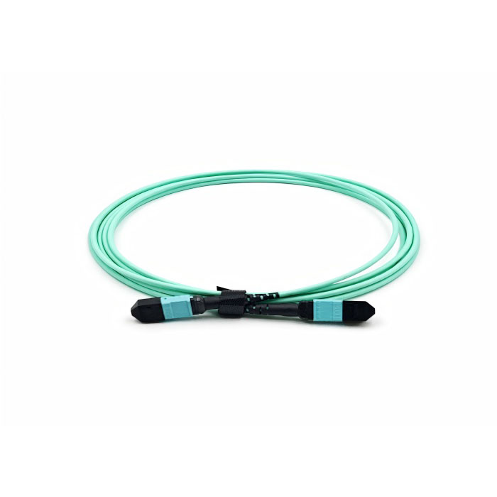
A replacement cord can fit the rack and still connect the wrong lanes or present the wrong mating interface. Give an MPO MTP patch cord supplier the actual endpoint requirements before approving a substitute. Feiyi’s MPO/MTP optical patch cord listing distinguishes SM and MM ferrules, standard and low-loss grades, polish choices and male/female housing kits. Confirm the fiber mode, pin arrangement, lane map and acceptable connection loss first. A cable color or familiar connector shell does not establish those properties.
This matters to data-center technicians, network contractors and distributors replacing dense fiber connections. The order should preserve the approved interface and transmission path. A manufacturer’s listing of application types does not independently guarantee the performance of a particular protocol across a completed channel.
An MPO MTP patch cord supplier should identify the actual connector rather than rely on a generic name
MPO describes a multi-fiber connector interface. MTP is a branded MPO connector family associated with US Conec. Feiyi’s combined product title identifies a product range to investigate, but it is not documentary proof of a particular connector brand in every supplied cord. If genuine MTP hardware is contractually required, request confirmed sourcing and the supplied connector identification.
US Conec’s technical FAQs explain the relationship between MPO and MTP and the role of MT ferrule alignment pins. Use this as general interface context. US Conec’s proprietary performance or field-change features should not be attributed to an unconfirmed generic MPO cord.
Male and female MPO ends should match the installed pin arrangement
Feiyi lists male and female kits. The order should identify the pinned and unpinned condition at each end and how it mates with the installed equipment. A connector’s external shell or boot color should not be used to infer the presence of pins. Confirm the actual mating arrangement before a replacement is brought to the rack.
Inspect the ferrule and pin condition through the approved safe inspection process, with the optical source disconnected as required by the system procedure. Do not force two incompatible ends into an adapter. Where field gender changes are possible on a particular branded connector, they should follow that connector’s approved method; generic availability of male/female kits does not make every supplied cord field-convertible.
SM and MM ferrule grades carry different reflection requirements
The Feiyi table distinguishes standard SM MT ferrules and low-loss SM MT ferrules in APC and PC polish forms. Standard SM entries list typical insertion loss of 0.50 dB and maximum 0.70 dB. Low-loss SM entries list typical 0.30 dB and maximum 0.50 dB. Identify which grade and polish are actually supplied rather than quote the favorable column for the entire range.
SM APC and PC reflection limits belong to different endfaces
The SM APC entries list 60 dB return loss, while SM PC entries list 45 dB. Preserve the selected polish at both interfaces. A familiar SM designation does not make the polished ends interchangeable.
MM low-loss ferrules retain the MM reflection condition
The MM entries use PC polish and list 20 dB return loss. Standard MM insertion loss is 0.50 dB typical and 0.70 dB maximum; low-loss MM is 0.30 dB typical and 0.50 dB maximum. Do not attach the SM APC return-loss value to an MM cord.
For a distributor, standard and low-loss items should be separate identities even when their housings appear identical. A customer’s channel budget may depend on the lower maximum. Receiving a standard-grade cord and describing it by the low-loss typical value changes the purchasing condition without acknowledging the substitution.
Insertion loss and return loss also answer different questions. Insertion loss concerns transmitted power through the connection; return loss concerns reflected power under the applicable measurement. A satisfactory insertion-loss result should not be taken as evidence that the required reflection condition is met.
MPO lane continuity must preserve the equipment’s approved path
The Feiyi listing does not provide one universal fiber count or an end-to-end polarity map for every cord. Confirm the ordered count, occupied positions and full endpoint mapping. Use the actual equipment’s required transmit and receive positions. A high-density connector standard does not select the correct complete-channel polarity for a particular installation.
A replacement MPO trunk needs the end-to-end map rather than a color convention
Consider a technician replacing a trunk between two existing panels. The old cable may have been selected to work with specific adapters, cassettes or patch connections. Copy the approved complete path and confirm how the replacement contributes to it. A cord’s standalone position mapping does not establish that the entire connected channel still routes transmit lanes to the intended receive lanes.
Use the confirmed endpoint view and key orientation in the drawing. A numbered position viewed from one end can be misread if the opposite end is drawn from a different perspective. Agree the viewpoint before interpreting a continuity test. If the system uses a recognized polarity method, identify the relevant components and confirm how their combined mapping achieves the required result.
US Conec’s MTP PRO interface documentation illustrates why field polarity changes are product-specific. Its methods apply to the identified connector family. Do not assume the same change procedure is available for an MPO assembly whose hardware has not been confirmed.
For receiving, request continuity results for each occupied position and retain any intentionally unused positions in the mapping. A successful optical reading through one lane cannot demonstrate the remaining lanes. Label the supplied ends so the installer can associate the tested map with the physical cord.
The MPO connector-loss column is not a complete-channel allowance
The product table identifies MPO connector performance. A completed link may include multiple mated connections, other cords, cassettes and fiber. Define which reference connections the cord test includes, then use the whole installed channel’s requirements. Do not multiply a favorable typical connector number and call the resulting subtotal a measured channel result.
A network buyer should work from the required receiver condition and the approved optical path. If the replacement introduces another connection, changes fiber mode or uses a different ferrule grade, revisit the route allowance. A product’s reference to 40G or 100G applications does not certify every fiber count, distance, transceiver or topology at that data rate.
Low-loss MPO acceptance should record individual lanes
Ask for results corresponding to the selected grade and supplied endpoints. An average across the ferrule can hide an individual lane outside its requirement. The low-loss maximum of 0.50 dB should remain attached to the relevant connector and agreed test condition, rather than described as a universal complete-cord limit without clarification.
Before repeating an abnormal reading, inspect and clean the connection according to the approved procedure. Dirt can affect one lane or several and can damage a mating interface if ignored. A dust cap protects handling but is not evidence that an endface is clean. Retain the lane identity when investigating the result so repeated measurements concern the same path.
The MPO table also lists exchangeability no greater than 0.3 dB. Keep that condition separate from the original insertion-loss reading. A sample tested against one reference connector may need confirmation when the installed mating partner changes. For a replacement program, define which reference and counterpart are used in acceptance so that a change in mating condition is not mistaken for a change in the cord’s approved grade.
Round, oval and ribbon MPO kits should be selected for the actual cable construction
Feiyi lists round housing kits with a connector length of 60.2 mm and 3.0 or 3.6 mm cable boot choices. The oval housing kit lists 45.6 mm connector length, while the bare-ribbon kit lists 43.0 mm. These entries distinguish kit forms; they should not be treated as a universal overall length for every completed cord.
A rack technician should establish clearance for the selected connector and cable exit behind the equipment or panel. A shorter kit dimension does not prove that the cable can tolerate an arbitrary bend immediately behind the boot. Request the assembly’s actual construction and handling requirement for the installed route.
MPO boot color can support identification but cannot prove fiber mode
The kit information lists multiple SM and MM boot colors, including custom choices. That makes color useful as an agreed local identification aid, but unsuitable as the only evidence of mode, grade or mapping. Preserve the written configuration on the unit record and receiving results. A customized color can otherwise create a misleading visual match to a different stock item.
The listed durability condition is no greater than 0.2 dB change after 500 matings under the cited test. This describes a durability qualification condition, not a promise that a contaminated installed connector can be mated indefinitely. Likewise, the tensile entry should not be converted into an installer instruction to pull on the ferrule or boot. Use the approved assembly handling requirements.
Single-fiber patch cords and PM instrument links are separate replacement decisions
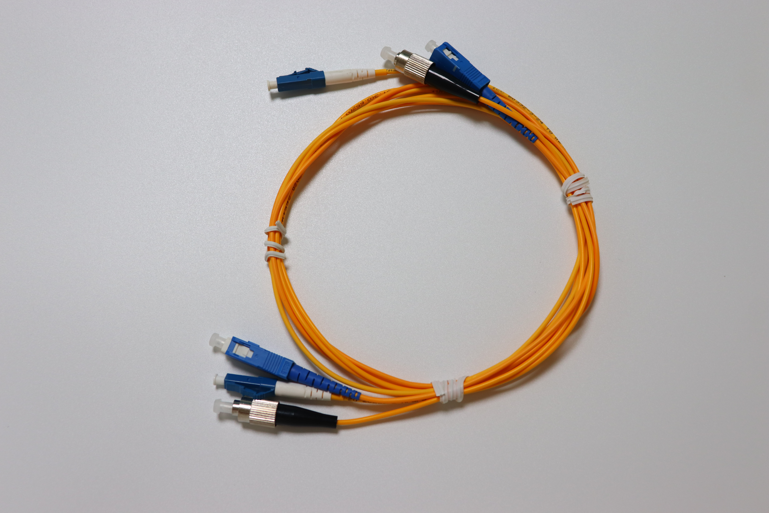
Feiyi’s ordinary optical patch cord family provides FC, SC, LC and other listed connector alternatives. It is relevant when the equipment terminates individual optical connections rather than a multi-fiber ferrule. Its connector loss and return-loss entries are separate from the MPO table; do not use them to certify an MPO interface.
The PM 1550 nm optical patch cord addresses a polarization-maintaining instrument interface. Standard MPO loss or continuity performance does not prove PM-axis orientation or extinction performance. A buyer moving a PM instrument into denser connections needs separate confirmed polarization documentation, not a generic MPO replacement.
Feiyi’s insert-type PLC splitter is another dense front-connection product, but it distributes optical power between branches. It does not replace an MPO lane-preserving interconnection. A distribution cabinet and a parallel optical channel can both have many connectors while performing fundamentally different routing jobs.
The replacement package should preserve the tested MPO interface until installation
Request protected ferrule faces and handling that avoids loading the connector and cable exit. Keep the end labels, pin condition, polish and map associated with the cord as it is coiled for delivery. A distributor shipping visually similar standard and low-loss variants should separate their identities, without claiming a stock quantity or factory packing method that has not been confirmed.
The MPO listing gives operation from −20 to +60 °C and storage from −40 to +80 °C. Those conditions should not be widened using the ordinary patch family’s different temperature table. Confirm the selected assembly for the equipment environment, including any requirement beyond the product’s stated component conditions.
Feiyi’s MPO/MTP connectivity explanation offers additional interface context. Approve the replacement when its pins, polish, mode, grade and lane path reproduce the required installed connection. If brand, polarity or fiber count is still inferred from a product title or color, resolve that identity before the cord reaches the service rack.