A MEMS Optical Switch Manufacturer Order Needs a Controller Boundary and a Confirmed Channel Count
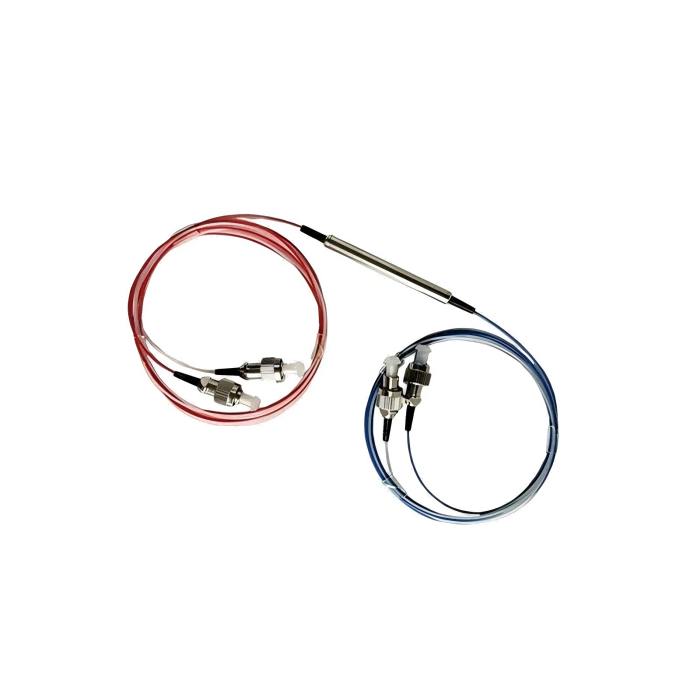
A MEMS optical switch can mean a small switching element, a controlled module or an instrument that already scans channels. Ordering the wrong boundary leaves the test system missing power, drive electronics or a usable control interface. A MEMS optical switch manufacturer discussion should therefore begin with the confirmed channel topology and exactly what the supplied unit includes. Feiyi lists a PM MEMS switching option and a separate MFSW-1×2 single-mode module. Confirm the selected build and controller scope before planning automated acquisition.
For an optical-test OEM, low insertion loss is only part of the decision. The order also needs a defined port map, fiber construction, supply interface and measurement timing boundary. A laboratory wanting a ready-to-use scanning instrument has a different requirement from an OEM embedding a DC-controlled module on its own electronics.
A MEMS optical switch manufacturer should confirm channel count before controller design
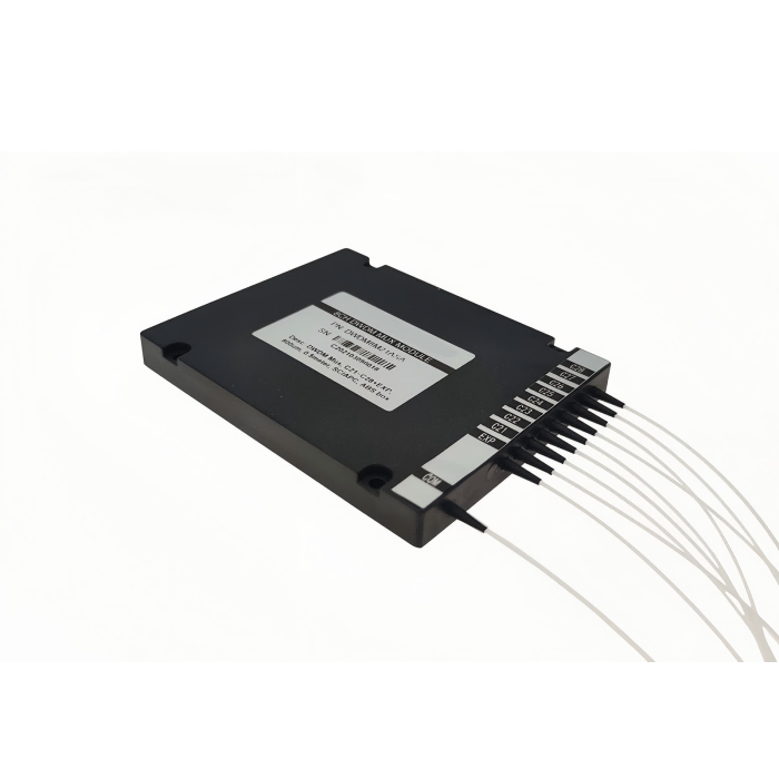
Specify the actual required topology, such as one common path selected among four outputs, rather than relying on a broad multi-channel description. For the Feiyi PM MEMS option, obtain the exact channel count, hardware revision and matched port drawing in the quotation or approved specification. Do not write a controller around a channel count inferred from an unconfirmed description or assume that one interface instruction applies to every variant.
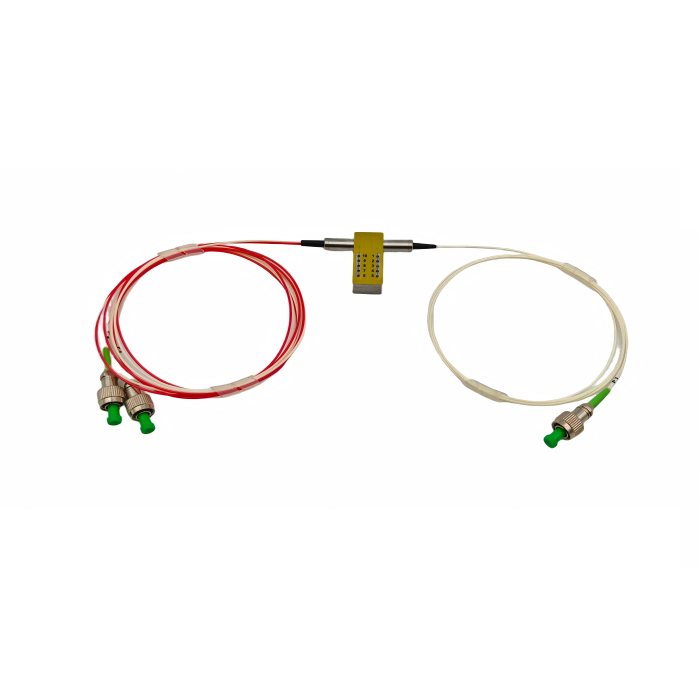
The PM MEMS entry identifies a 1550 ±20 nm band, PM1550 fiber and FC/APC connectors with slow-axis alignment. These are useful starting requirements for a polarization-sensitive test path. The complete supplied module still needs its own confirmed topology and performance conditions. A slow-axis connector statement does not establish every internal route’s polarization behavior or approve a particular acquisition sequence.
The PM MEMS module needs a selected build, not a universal timing number
Ask which switching-time definition applies to the quoted hardware and how it relates to stable optical output. Separate a command response from route settling and the subsequent detector measurement. If several timing statements are supplied, the manufacturer should reconcile them for the selected version. Avoid choosing the shortest entry and declaring it the test system’s complete waiting interval.
For a hypothetical multi-channel PM instrument, write the required acquisition behavior independently of the supplier’s raw command format: select the intended channel, establish the defined valid-route condition, then measure under the receiver’s requirements. That is an engineering specification to confirm. It is not an executable control recipe for an unapproved module or a claim that a debugging signal proves optical stability.
MEMS module procurement should separate DC hardware from a complete optical instrument
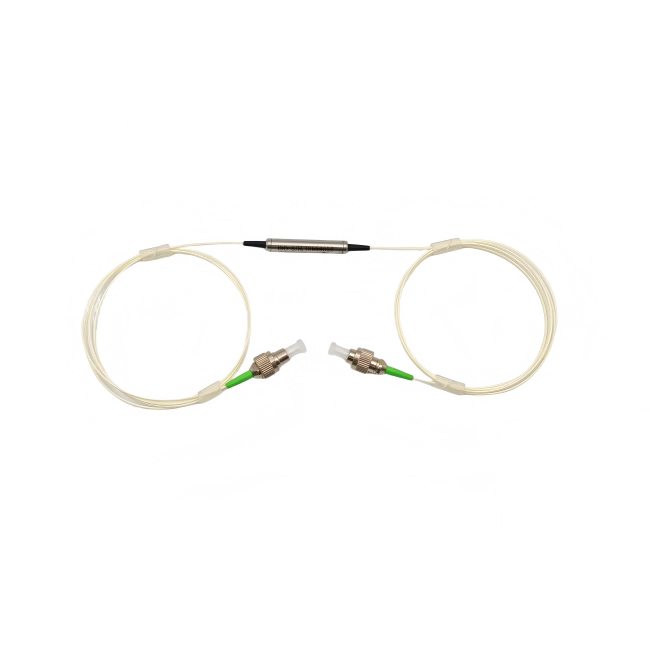
Feiyi’s MFSW-1×2 single-mode module lists 1260–1650 nm operation, tests at 1310/1550 nm, 9/125 µm single-mode fiber and FC/PC connections. It gives 500 ±50 mm lead length, insertion loss no greater than 1.0 dB and a DC 5 V ±5% supply. This is a controlled-module reference. It should not be called a PM substitute or assigned a MEMS internal construction without confirmation.
That module describes UART or parallel control and a digital pin interface. An OEM choosing it takes responsibility for integration with its own electronics and software. The complete test path includes the module, connected leads, source and receiver; the module’s published loss limit does not establish all of those elements. Preserve this boundary when comparing a compact module quote with an instrument price.
FSW-1×8-T-S offers scanning functions that an embedded module may not include
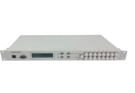
The FSW-1×8-T-S optical switching instrument lists an LCD, automatic scanning, configurable start/end channels and a device address for serial control. It lists FC/PC optical interfaces, RJ45 and RS-232 monitoring ports, and an AC supply of 85–264 V at 50/60 Hz. These are instrument-level features, not implicit features of a small MEMS switching component.
The instrument specifies a 19-inch 1U chassis of 483 ×200 ×44 mm. Its published switching time of no more than 10 ms is stated for adjacent sequential switching. Retain that condition when evaluating a scan plan; it should not be interpreted as a universal arbitrary-channel acquisition interval. Confirm the chosen instrument’s control documentation and optical settling requirements for the actual measurement sequence.
Control-interface approval should identify logic levels and status meaning
The MFSW-1×2 module specifies UART or parallel TTL-style control and identifies LVTTL input thresholds: a minimum 2 V logic high and a maximum 0.8 V logic low. That detail matters when connecting another controller. A module supplied at 5 V does not mean that every interface signal can be treated as a supply pin, or that an unrelated controller’s output limits are automatically compatible.
Its pin description includes a mode input, reset input and a ready output identified for internal debugging. The OEM should obtain the approved operational status definition instead of making the debugging output a production measurement trigger. Ask which state reports command acceptance, which indicates route selection and which, if any, can be used to determine when the optical result is valid.
Serial-port names do not make module and rack protocols interchangeable
Feiyi’s OSW-8×7 rack-mounted switch lists RS-232 monitoring with a model-specific command description. The 1×2 module instead exposes UART and parallel interfaces. Serial communication at both boundaries does not mean they share electrical wiring or command syntax. A controller file must identify the selected device and approved protocol revision.
The rack unit’s optical interfaces are LC/PC, with eight input identifiers and grouped output interfaces. It lists an AC 220 V supply and a 483 ×303 ×44 mm chassis. These differences affect installation and control integration. Use it as a complete switching-system alternative where that layout serves the project, without claiming that its ports or command examples define a smaller MEMS module.
Compare a MEMS request with mechanical alternatives by the required test job
The FY-FSW-1×2 mechanical switch offers 3 or 5 V and latching or non-latching versions. It can be relevant when the requirement is a defined two-destination path and its stated performance fits the system. Choosing a MEMS label alone is not a substitute for comparing optical paths, controller scope, environmental conditions and expected use.
The mechanical SM entry lists a maximum insertion loss of 1.0 dB and switching time no greater than 8 ms. The MFSW-1×2 module lists no more than 30 ms switching time and repeatability of ±0.1 dB, while the scanning instrument has its separate adjacent-channel timing condition. These entries belong to different selected products. They should not be merged into a fictional switch that combines every family’s most favorable figure.
Sercalo’s MEMS switch explanation describes a silicon-mirror switching approach and its device-specific drive conditions. Agiltron’s MEMS documentation provides another construction and configuration reference. These sources help an engineer understand why the switching technology and drive boundary should be identified. Their speed, reliability qualifications or electrical arrangements are not Feiyi specifications.
Optical acceptance belongs to every selected channel, not only the control connection
A successful serial response proves a control event only within its documented meaning. It does not establish that the intended optical channel is connected with acceptable loss. Define a sample acceptance that verifies the physical common-to-output map and the required optical values at the selected wavelength. For a PM request, add the axis and polarization condition for those actual routes.
The MFSW-1×2 module lists crosstalk of at least 50 dB and return loss of at least 50 dB. The scanning instrument lists crosstalk of at least 55 dB and return loss of at least 50 dB. Keep route, device and measurement conditions attached to those entries. The rack system includes monitoring functions with their own accuracy specification, which should not be used as a replacement for an independent optical acceptance definition.
For a laboratory choosing the complete scanning instrument, preserve the channel range, scan direction and measurement delay in its test configuration. For an OEM choosing an embedded module, specify the source and detector handoff as part of the host-system design. The first buyer may prioritize ready-to-use controls; the second may prioritize compact interfaces. They should not receive the same assertion that the switch alone solves automation.
Lead routing is part of that integration. The MFSW module specifically cautions against excessive fiber bending. Agree the installed routing and support for its 500 ±50 mm leads. For a rack system, plan connector access and service loops around the selected chassis. Request protection appropriate to exposed module leads or instrument interfaces, instead of applying one packing description to both boundaries.
Module electrical consumption and optical input power are different 500 mW limits
The MFSW-1×2 description lists electrical consumption below 500 mW and maximum optical handling no greater than 500 mW. These similarly sized numbers describe different quantities. The host supply must meet the electrical requirement; the source path must stay within the approved optical condition. A favorable consumption figure cannot be used as an optical-power rating, and a detector measurement cannot establish the module’s electrical supply behavior.
The OSW-8×7 rack unit lists an optical monitoring range of −50 to +23 dBm and accuracy entries that change across that range. The higher-range entry is no greater than 0.5 dB between +23 and −40 dBm, with a different limit down to −50 dBm. These belong to its monitoring function. They should not be used to claim that the rack’s internal monitor verifies a PM module’s axis or every independent optical acceptance quantity.
The rack product also lists a maximum insertion-loss entry of 15 dB. That is a system entry requiring its selected route conditions, not the 1.0 dB module limit. A laboratory comparing the rack system with an embedded selector needs to preserve the different optical boundaries and functions. Ask which complete route the rack limit covers, rather than accepting the module’s smaller number as a substitute for a larger system’s published specification.
The scanning instrument offers selectable baud rates including 1200 and 115200, while the embedded-module interface has its own definition. Ask which communication setting and addressing method apply to the selected build. The laboratory using several addressed scan instruments faces a different control problem from an OEM wiring parallel inputs. Preserve those boundaries in the quotation so a shared serial terminology does not conceal missing integration work.
For the PM MEMS sample, retain the supplier-confirmed channel diagram and control revision alongside the measured optical routes. If the channel population changes later, reopen both the controller definition and the channel tests. Passing one approved sample does not establish another topology whose route numbers or status meanings differ. This keeps the procurement decision tied to the hardware that the test system will actually receive.
Feiyi’s optical-switch technology comparison offers broader context. For the order, retain the confirmed channel count, selected fiber, exact supplied control boundary and accepted optical timing condition. If a document describes another variant or leaves the status meaning open, resolve that specific point before committing the controller design. The right switch order ends with a usable hardware interface, not just a technology name.