Wedge Lensed Fiber Supplier: Match the 60-to-120-Degree Wedge to the Laser Diode Far Field
[Reading 58 lines from start (total: 58 lines, 0 remaining)]
Wedge Lensed Fiber Supplier: Match the 60°–120° Wedge to the Laser Diode Far Field
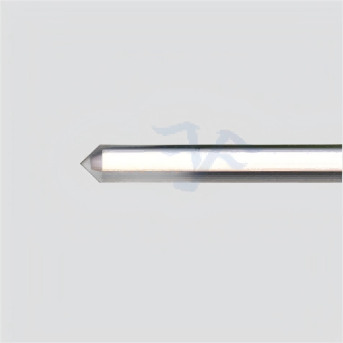
A wedge lensed fiber supplier needs the source beam before the fiber tip can be designed intelligently. Feiyi’s Wedge Lensed Fiber is intended for fiber-laser and DFB-laser coupling and lists a tip radius of curvature from 8 to 12 µm, a wedge angle from 60° to 120°, and an applicable coupling far-field divergence of 15° to 40°. The product can be made from SM, MM, PM or customized fiber, with optional FC, LC, SC and SMA connector families and PC/APC variants.
For a buyer, those dimensions should be tied to the actual laser diode rather than selected independently. A diode with a strongly elliptical far field needs a different coupling strategy from a nearly symmetric source. The wedge surfaces reshape the interface seen by the fast and slow divergence axes, so source wavelength, far-field angles, desired coupling direction and target fiber mode should be supplied together.
A wedge lensed fiber supplier should start from the diode’s two divergence axes
Laser diodes commonly emit an asymmetric beam with different fast-axis and slow-axis divergence. External wedge-fiber documentation describes the wedge surfaces as a way to better match that elliptical output and improve coupling. Feiyi’s own page expresses the compatible far-field range as 15°–40°, which gives the buyer a practical starting boundary for discussing the source.
Do not compress the source description into one average divergence number if the two axes are very different. Put both far-field values on the optical drawing, together with the orientation of the diode relative to the wedge. That allows the supplier to understand which facet is correcting which direction.
Fast-axis and slow-axis labels should survive the handoff from laser drawing to fiber drawing
A laser data sheet may define horizontal and vertical divergence while the fiber drawing uses another coordinate system. Translate those axes explicitly. If the wedge is rotated 90° from the intended orientation, the fiber can have the correct dimensions and still couple poorly.
The 60°–120° wedge range should be chosen from coupling geometry, not from a favorite nominal angle
Feiyi lists a customizable wedge angle from 60° to 120°. The best value depends on the source far field, the desired spot transformation and the mechanical orientation between diode and fiber. A buyer should not specify 90° simply because it lies in the middle of the range.
For a prototype, it can be useful to evaluate a small set of nearby geometries if the source model or alignment tolerance is uncertain. Once a design is approved, freeze the wedge angle and orientation in the controlled item so later lots do not drift toward a different coupling solution.
The wedge angle and tip radius should be treated as a pair during optimization
Feiyi also lists tip radius of curvature from 8 to 12 µm. Radius affects the local lens action while wedge angle affects the anisotropic geometry. Changing one dimension while holding the other only by habit can move the coupling optimum. Keep both values in the sample record.
Tip radius should be linked to the required spot at the fiber mode, not copied from another DFB package
A radius of 8–12 µm is a compact micro-optical feature. Small changes can alter how the source is focused into the fiber. When the buyer has mode-field or coupling-target information, provide it with the laser far field so the supplier can evaluate the tip as a complete optical interface.
If the end use changes from single-mode signal coupling to multimode illumination, the old radius and wedge geometry may no longer be appropriate even if the diode wavelength remains similar.
SM, MM and PM versions should be separated by the receiving optical system
Feiyi allows single-mode, multimode, polarization-maintaining and customized fiber. A DFB source intended for a single-mode communications or sensing path should not be coupled into a multimode wedge fiber simply because alignment appears easier. The fiber mode is part of the delivered optical function.
For a PM build, add the polarization-axis requirement to the wedge orientation. The diode’s polarization, the fiber axis and the wedge facets become one coordinate problem. If the PM axis is left out of the drawing, a mechanically correct sample can still enter the downstream system with the wrong polarization reference.
Reflection control should be discussed separately from coupling efficiency
External wedge-lensed-fiber documentation notes that wedge or angle-wedge geometry can help direct reflected light away from a laser source. Feiyi also offers direct coating on the processed bare-fiber endface. These are useful tools, but a buyer should not assume that the geometry which maximizes coupling automatically gives the lowest source feedback.
If the laser is sensitive to reflected light, state the reflection concern and source wavelength in the request. The supplier can then evaluate wedge orientation and any coating requirement together. The acceptance plan may need both coupling efficiency and reflected-light behavior rather than one power reading.
A coating request should name the wavelength band that the coating must serve
Feiyi can deposit thin films on the bare-fiber surface. A coating chosen for one DFB wavelength should not be silently reused after a source change. Keep the optical band, coating purpose and wedge geometry together in the configuration record.

Direct bare-fiber processing matters when the tip must stay compact and clean
Feiyi states that its lensed-fiber processing does not use auxiliary adhesive on the bare-fiber tip. That keeps the optical microstructure compact and avoids an additional organic material at the immediate optical surface. For assemblies with tight laser-to-fiber spacing, that geometry can be more important than the connector style at the remote end.
The buyer should still define how the finished tip is mounted. A delicate wedge can be damaged by a clamp or by an assembly process that was originally designed for a flat-cleaved fiber.
The connector is a service interface, while the wedge tip is the coupling interface
Feiyi lists FC, LC, SC and SMA options with PC/APC variants. In a connectorized assembly, the purchase drawing should identify which end carries the wedge and which end connects to test equipment, a pigtail or the rest of the optical system. Do not let the connector description replace the custom-tip specification.
For a bare-fiber OEM assembly, specify finished fiber length and stripped length according to the holder and laser package. Feiyi states that both can be customized. Too little stripped length can prevent positioning; too much can leave the fragile fiber unsupported.
DFB laser coupling should be qualified with the production package spacing
A wedge sample aligned on a laboratory six-axis stage can perform well even if the production holder has less adjustment range. The buyer should therefore repeat coupling validation with the real or representative laser-to-fiber spacing and mechanical datum before approving volume production.
Record the source package, nominal gap, wedge orientation and fiber-tip position when the optimum is found. That gives manufacturing a reproducible target instead of only a peak coupling number from an open bench.
Alignment tolerance can matter more than the absolute best coupling point
A geometry with the highest peak efficiency may be difficult to hold in production if the acceptable alignment window is extremely narrow. If the product needs repeatable assembly, compare coupling performance over the expected placement tolerance rather than at one ideal position.
The -40 to 85 °C range should be tied to the final fiber, coating and mounting scheme
Feiyi lists an operating temperature range of -40 to 85 °C and relative humidity from 0 to 85%, together with a statement of compliance with Telcordia GR-1221 and GR-63 Core environmental or reliability testing. A buyer should preserve those site-stated conditions in the product file, but the final module can still add stresses that are not represented by a bare-fiber component test.
If the wedge tip is bonded into a laser package, confirm that the mounting process and any added coating are compatible with the application’s environmental range. For a laboratory DFB coupling assembly, cleanliness and handling may dominate the practical risk instead.
Incoming inspection should separate geometry verification from optical alignment
Before adjusting the diode or fiber stage, verify the fiber type, wedge angle, tip radius, wedge orientation, connector or pigtail construction and coating identity. A microscope or approved reference image can help confirm that the wedge is oriented correctly. Then perform the coupling test under the approved source and alignment conditions.
If the geometry is wrong, changing the alignment fixture can temporarily hide the problem and make the next batch harder to reproduce. Keep the supplier drawing and the optical test as two connected but distinct checks.
Shipping protection should keep the 8–12 µm tip-radius region away from contact
The functional lens is formed directly on a very small fiber tip. If the project needs a protective cap, tube, ferrule clearance or tray, put that handling requirement in the purchase drawing. The packaging should prevent the wedge surfaces from touching hard material or neighboring fibers during transit.
At the receiving station, leave the tip protected until inspection equipment is ready. A small chip or contamination at the lensed region can change the coupling result and be mistaken for an incorrect wedge angle.
A wedge lensed fiber is not the right answer when the required output is a deliberately rectangular far field
Feiyi’s Four-Faceted / Pyramidal Lensed Fiber lists a rectangular far-field pattern as a configurable result and is aimed at high-power laser-diode coupling. If a project specifically needs a rectangular spot, that geometry deserves comparison with the two-facet wedge rather than forcing the wedge to solve a different beam-shaping problem.
Similarly, the Angled Lensed Fiber is better suited when the main need is endface tilt, beam deflection or back-reflection control without the same wedge-lens objective.
The product family should be selected from the desired far field before the connector is selected
Connector choice is usually easy to change late in a project. Fiber-tip geometry is not. Freeze the required output shape and source coupling first; then choose FC, LC, SC, SMA or a bare-fiber termination that fits the integration plan.
A repeat wedge-fiber order should preserve the laser source as part of the specification context
Once a coupling design is approved, retain the source wavelength and package, fast- and slow-axis divergence, selected 60°–120° wedge angle, 8–12 µm tip radius, fiber type, wedge orientation, coating requirement, connector or bare-fiber construction, finished length and stripped length. If the part is PM fiber, keep the polarization-axis reference as well.
A replacement request described only as “wedge lensed fiber” loses the reason the micro-optic worked. The useful purchasing file is the one that lets the next engineer reconstruct the diode-to-fiber geometry and understand which dimensions are optical requirements rather than drawing cosmetics.
A supplier sample plan should test the geometry that is hardest to assemble, not only the nominal center point
When several wedge angles or tip radii are being evaluated, define the same source, holder and measurement method for every sample. Record both peak coupling and the amount of alignment correction required to reach it. A sample that reaches a high peak only after excessive tilt or translation may be less suitable for a fixed production holder than a slightly lower peak with a wider alignment window.
This comparison is especially useful before the laser package and fiber mount are tooled. It keeps the final wedge geometry tied to a buildable assembly rather than to the best result obtained by an unrestricted laboratory stage.
[executed on device: SK-20260121JOTG (a251fff9-956e-47b5-9307-14fb53329ed2)]