PM WDM Supplier Selection Starts With a Wavelength Map, Not a Channel Count
A three-port component can combine a pump and signal, separate two distant wavelength bands, or select a closely spaced transmission channel. Those jobs require different specifications even when the package looks similar. For an OEM comparing a PM WDM supplier, the first document should be a wavelength-to-port map: what enters each lead, which band must pass, which band must reflect, and how the polarization-maintaining axes connect to the rest of the assembly. Begin with Feiyi’s PM filter WDM for separated bands, or its 100/200 GHz PM DWDM three-port device when the project concerns grid-based channel selection.
The common connection, pass-band connection and reflection-band connection need explicit names on the drawing. Lead color can support identification, but the approved routing diagram must establish what each connection does.
Give the PM WDM supplier the pass band and reflection band separately
In a filter WDM, the desired route depends on wavelength. The pass-band lead and reflection-band lead join at the common connection when the component is used for combining. In a separating arrangement, the common connection receives the multi-wavelength signal and the wavelength-specific routes carry their assigned bands. The intended direction must still be confirmed for the selected device; the word “WDM” does not establish every possible connection as an approved operating path.
Thorlabs’ PM WDM technical explanation describes the common-port relationship and why signals must fit the specified wavelength regions. Apply that general principle to the order drawing. It does not supply Feiyi’s individual device ratings or establish that a selected filter will accept an arbitrary extra wavelength.
The PM 1064 nm three-port WDM pairs its signal route with a 980 nm reflection route
Feiyi’s PM 1064 nm three-port device lists 1064 nm as the channel wavelength and 980 nm as the reflection wavelength. Its fiber options identify PM980 and PM1060. That combination gives an optical equipment buyer a concrete starting point for a 980/1064 nm routing requirement, but the exact source spectrum and accepted operating bandwidth still need to appear in the confirmed specification.
Consider an assembly engineer receiving a pump-source drawing from one team and a signal-path drawing from another. If purchasing combines them into a single line saying “1064 nm WDM,” the 980 nm connection can disappear from the order description. Instead, show the pump connection, signal connection and shared connection together. Record which fiber belongs to each path and where each lead terminates in the assembly.
The three-port listing specifies a maximum pass-channel insertion loss of 0.8 dB and reflection-channel insertion loss of 0.6 dB. These are two path requirements, not a single averaged loss number. A sample with an acceptable pass path but an unsuitable reflection path can still be wrong for the assembly. The measurement record should retain the two port pairs and their associated test wavelengths.
A PM filter WDM band is different from a 100 GHz DWDM channel
Feiyi’s PM filter WDM range includes broad wavelength pairings, such as a 1020–1080 nm channel range with a 960–990 nm reflection range, and a 1950–2050 nm channel range with a 1570 ±10 nm reflection range. The 100/200 GHz PM DWDM device instead lists ITU-grid channel selection and specified channel spacing. One decision concerns separated spectral bands; the other concerns closely spaced channels on a defined frequency grid.
100 and 200 GHz specify channel spacing, not a 100G or 200G data rate
The “100G–200G” wording in the PM DWDM product name refers to the table’s 100 GHz and 200 GHz channel-spacing choices. Do not translate that into a guaranteed transmission data rate. The optical component’s passband must be checked against the actual signal spectrum, channel center and transmitter behavior. Data rate alone does not describe all of those conditions.
ITU-T Recommendation G.694.1 defines the frequency-grid context for dense wavelength division multiplexing. A channel requirement should therefore identify the intended grid position and spacing rather than only an approximate wavelength label. This is a channel-identification issue; citing the grid does not establish an independently tested compliance certificate for the supplied component.
| Feiyi PM wavelength route | Published spectral description | Decision to resolve |
|---|---|---|
| PM filter WDM | Several separated pass/reflection bands | Which pair fits the pump, signal or instrument spectrum? |
| PM 1064 nm three-port device | 1064 nm channel; 980 nm reflection | Which lead carries each wavelength and which connection is common? |
| PM 2000 nm three-port device | 2000 nm channel; 1550 nm reflection | Are the two operating spectra and their fibers agreed? |
| PM 100/200 GHz DWDM device | ITU grid; 100 or 200 GHz spacing | Which center channel and passband are required? |
A narrow-channel instrument should not substitute the broad filter WDM merely because both route light by wavelength. Conversely, a widely separated pump/signal pair does not become a dense-channel project because the product label includes DWDM. Procurement should preserve the actual spectral task and obtain a matching device-level specification.
The existing Feiyi explanation of filter WDM operation provides background on wavelength routing. Use it alongside the selected product details, while keeping the project-specific passband, fiber and power decisions in the order itself.
Preserve the PM-axis reference through the WDM’s three connections
Wavelength routing and polarization alignment are separate approval questions. Feiyi’s PM filter WDM and PM grid-channel device list PM Panda fiber, fast- or slow-axis options and a minimum extinction ratio of 18 dB. A buyer must connect those fields to the actual source and downstream component axes. A correct spectral route does not compensate for an incompatible polarization reference at an interface.
PM1550 jumpers identify an interface, not the WDM’s spectral approval
Feiyi’s PM 1550 nm optical patch cord can provide the relevant jumper starting point for a 1550 nm PM connection. Specify its connector polish, axis reference and length against the WDM end it will mate with. The jumper’s wavelength designation does not establish the filter’s channel bandwidth, isolation or reflection-band behavior.

AFW Technologies’ PM filter WDM documentation illustrates why pass/reflection definitions, fiber choices and connector-axis information belong together in an order. These are general specification principles. Feiyi’s accepted drawing and product data must supply the actual build details; another manufacturer’s port conventions should not be transferred silently.
For an instrument builder extracting a narrow telecom channel, identify the axis reference at the common input and at the selected output. If a connectorized test lead is added during acceptance, record that lead and its orientation. Otherwise, a change in the test connection can be mistaken for a change in the device. Keep the measured extinction-ratio condition traceable to the selected axis and wavelength.
An end-to-end measurement may be useful for the finished assembly, while a device-only measurement helps isolate component performance. Decide which result the purchase specification requires. Do not compare a bare-fiber catalog value to a complete connectorized link without accounting for the extra interfaces and the stated measurement conditions.
Check WDM rejection at the wavelength that could reach the wrong receiver
Feiyi’s PM grid-channel device lists adjacent-channel isolation of at least 30 dB and non-adjacent isolation of at least 40 dB. Those separate values matter when a receiver must reject neighboring channels. They should not be collapsed into a generic “high isolation” statement or assumed to describe pump rejection in a widely separated band device. The test must address the unwanted light that can actually arrive at the receiving connection.
The PM 2000 nm WDM needs its own 1550 nm rejection and fiber decision
The PM 2000 nm three-port WDM lists a 2000 nm channel and a 1550 nm reflection wavelength, with PM1550 and PM1950 appearing in the ordering information. It is a separate product route from the 980/1064 nm device. Confirm the approved fiber on each lead and the permitted spectrum instead of moving a previously accepted 1064 nm order description into the longer-wavelength project.
The listing shows maximum pass- and reflection-channel insertion losses of 0.8 dB. Its 300 mW maximum power-handling entry is not permission to use an unspecified amplified or pulsed source. Identify total power, wavelength distribution and operating mode at the device, then obtain the required confirmation for the selected configuration. The two sources can contribute to the common-path condition when the component is used to combine them.
AFW’s DWDM technical information separates passband, channel spacing and adjacent/non-adjacent rejection. Use the same distinction when planning a PM channel-device acceptance test. The published center-channel result is not evidence that every offset wavelength has identical loss or isolation.
A practical scan should be proposed around the actual source range and the receiver’s rejection concern. Ask the engineering team to define which channel centers or band edges need recording. A full spectral plot can be useful, but purchasing should not invent a required scan interval or a claimed plot that the supplier has not agreed to deliver. Start with the operating spectra and convert them into explicit acceptance points.
PM DWDM passband width must accommodate the signal beyond its nominal center
The 100/200 GHz device lists a passband at the −0.5 dB condition of more than 0.3 nm for the 100 GHz option and more than 0.5 nm for the 200 GHz option. Compare the applicable value with the transmitter’s occupied spectrum and permitted center drift. A source positioned at the nominal channel center during one bench check can approach a filter edge under another operating condition. Keep the required spectral envelope in the approval file; do not replace it with a single center-wavelength loss measurement.
Release the PM WDM order with both optical paths and their physical ends resolved
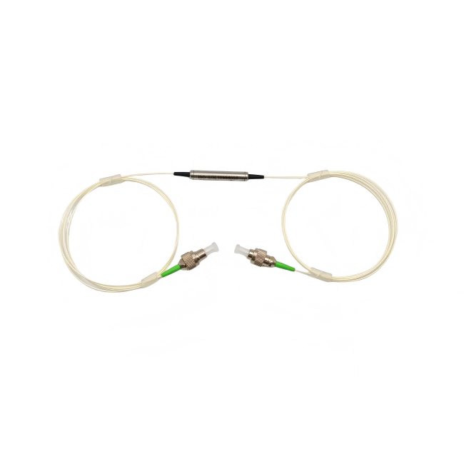
Feiyi’s PM filter and three-port listings show a cylindrical package of approximately 5.5 ×38 mm, along with lead-length and connector choices. Record the selected housing, exit directions and individual lead lengths against the instrument layout. A common lead that reaches the splice tray and two wavelength leads that reach separate subassemblies may require different routing provisions even when the catalog presents one nominal lead-length field.
Before shipment, request identification that keeps common, pass and reflection leads distinct through unpacking and assembly. Ask for connector protection appropriate to the selected ends and protection for any bare PM fibers that will be spliced. These are requested delivery controls, not claims about Feiyi’s standard packaging. A photograph of the finished lead identification can support receiving, but it cannot replace the optical routing test.
A distributor handling multiple WDM pairings should keep the wavelength map attached to the device description. Similar housings and connector colors are poor substitutes for the approved pass/reflection bands. Separate the 980/1064 nm, 1550/2000 nm and ITU-grid variants in the stock record, including their PM fiber and axis requirements, so a replacement is selected from the optical specification rather than appearance.
The order is ready when the supplier and buyer can trace each required wavelength from its physical input to its intended physical output, then identify the PM axis, permitted loss, unwanted-band rejection and operating power for that route. If one of those connections is still described only as “the other port,” resolve it before approving the component. That clarification is more valuable than selecting a familiar package around an incomplete wavelength description.