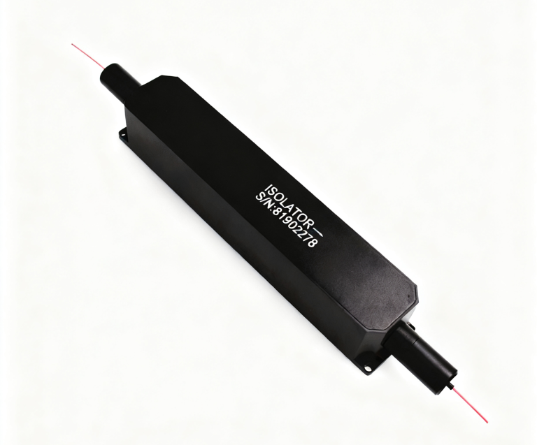
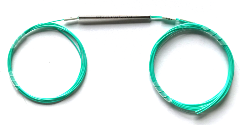
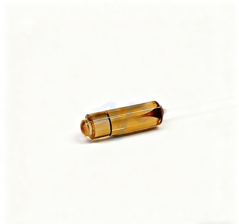
PM 1064nm Fiber Coupler Manufacturer: Specify the Split Ratio Before the Package
A PM 1064nm fiber coupler manufacturer needs to know the required split before the buyer chooses a package or connector. Feiyi’s PM 980/1030/1064nm Coupler supports 1×2 and 2×2 configurations, coupling ratios from 1% to 50%, PM980/PM1060 fiber choices and several package formats. For a 1064 nm laser, sensor or test instrument, the split ratio determines how much power remains in the main path and how much is sent to the secondary path. That decision should be fixed before the mechanical details.
A 50/50 device, a 10/90 monitor tap and a 1/99 tap are not interchangeable even when all are described as “1064 nm PM couplers.” The supplier should receive the intended optical function, the port configuration, the accepted ratio tolerance, the working polarization condition and the source power. Connector polish, pigtail length and package can then be selected around that optical requirement.
A PM 1064nm fiber coupler manufacturer order starts with the coupling ratio and port map
Feiyi lists 1×2 and 2×2 port configurations. A 1×2 coupler has one input and two output paths; a 2×2 version has two inputs and two outputs, which can be useful in bidirectional or more complex instrument layouts. The purchase drawing should name the ports and show where the high-power and low-power branches go. Do not let “1×2” or “2×2” become a substitute for a route drawing.
The product page lists coupling ratios from 1% to 50%. A buyer who needs a small monitoring tap should specify which output is the tap and which remains the through path. For a 50/50 design, both outputs may be equally important. These are different acceptance cases, so the inspection record should identify the expected loss on each branch rather than record one generic coupler reading.
A 10/90 monitor tap should be accepted differently from a 50/50 split
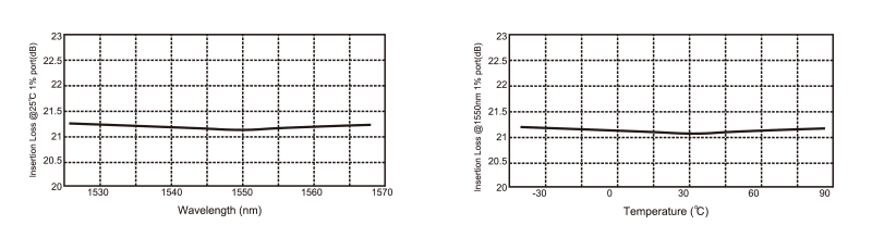
Feiyi’s conversion table shows how insertion loss changes with coupling ratio. For P grade, the listed 50/50 case is 6.8/6.8 dB, while 10/90 is 10.8/0.6 dB and 1/99 is 21.0/0.2 dB. A small tap is therefore designed to leave most of the power in one path. An incoming inspection that expects equal outputs would wrongly reject the component.
The exact ratio tolerance also matters to the instrument. If the low-power branch feeds a detector whose calibration assumes a certain percentage of the source, write that percentage into the controlled item. A generic “tap coupler” label is not enough for repeat orders.
Low excess loss should be kept separate from the intentional split loss
Feiyi lists typical excess loss of 0.07 dB for P grade and 0.1 dB for A grade in the standard coupler table. Excess loss describes additional loss beyond the intentional power division; it is not the same as the insertion loss seen on a branch after a 50/50, 10/90 or 1/99 split. Buyers should keep those concepts separate when comparing a coupler with the rest of a 1064 nm power budget.
For a 90% through path, a low branch insertion loss is expected, while the 10% monitor branch naturally has much higher insertion loss because less power is intentionally directed there. Calling that high branch loss a manufacturing defect would confuse the designed split with unwanted excess loss.
DK Photonics’ 1064 nm PM fused-coupler documentation provides useful industry context: PM fused couplers are specified by coupling ratio, port configuration and polarization behavior, not by wavelength alone. DK’s numerical values belong to its products; Feiyi acceptance should use the Feiyi specification and ordered ratio.
Directivity and polarization sensitivity should remain independent acceptance lines
Feiyi lists directivity of at least 55 dB and polarization sensitivity of 0.15 dB for P grade and 0.2 dB for A grade. Those values address different behaviors. Directivity concerns unwanted reverse coupling between ports, while polarization sensitivity describes how the split/loss responds to polarization. A power-ratio test alone does not prove both.
PM980 and PM1060 choices should match the adjoining 1064 nm fiber chain
The Feiyi page lists PM980 and PM1060 fiber choices. A 1064 nm buyer should compare the coupler pigtail to the source fiber, amplifier fiber, patch cord or sensor fiber on each side. A wavelength match does not guarantee that every PM fiber transition is identical. If a splice is required between PM980 and PM1060, the engineering drawing should identify it and preserve the axis reference.
For a test bench that uses removable connectors, the connector key can become the practical axis reference. For an OEM module that is fusion-spliced, splice orientation and fiber markings may be more important. The manufacturer should not be expected to infer the buyer’s axis convention from the word “PM.”
Extinction-ratio acceptance should be tied to the selected grade and launch condition
The Feiyi standard table lists a minimum extinction ratio of 20 dB in the P-grade column. To make that useful, the buyer should define the intended PM launch axis and the measurement reference. A result obtained with uncontrolled input polarization cannot demonstrate the same performance as the system’s actual polarized launch.
Package D, E, F and G solve different mechanical integration problems
Feiyi lists several package choices: Package D at 3 × 45 mm, E at 3 × 54 mm, F at 3 × 60 mm and Package G as a 10 × 20 × 90 mm case. D and E are associated with 250 µm bare fiber, F can use 250 µm bare fiber or 900 µm loose tube, and G supports larger cable or loose-tube options. The buyer should select the package from the installed environment rather than from whichever body is smallest.
A compact sensor head may favor an in-line tube and controlled bare-fiber routing. A rack instrument may benefit from a protected case and thicker cable. If the prototype changes package before production, recheck pigtail exits, service loop and connector location. Mechanical changes can alter how the fiber is stressed even when the optical coupler core is unchanged.
Fiber length and connector polish should be recorded as part of the 1064 nm coupler identity
Feiyi lists pigtail lengths of 1, 1.5 and 2 m in the standard table and ordering examples of 0.5, 1 and 2 m. Connector options include FC/PC, FC/APC, SC/PC and SC/APC. A buyer should state the finished length and connector finish expected on each port. “Standard connector” is not sufficient when a calibrated instrument depends on a known reflection condition.
A distributor stocking multiple ratios should not use cable color or connector type as the primary identifier. A 50/50 and 10/90 coupler can look identical externally. Put wavelength, ratio, port count, grade, fiber and connector in the stock description so a picking error is visible before shipment.
Temperature range and ratio stability should be evaluated together for field sensors
Feiyi lists an operating and storage range of -20 to +80 °C for this coupler family. A laboratory instrument may remain near room temperature, but a distributed sensor or outdoor enclosure can see a much wider range. If the split ratio feeds a reference detector, even a modest ratio change can affect the interpretation of that reference. The buyer should therefore define the environmental range in which the ratio matters instead of treating temperature as a separate mechanical note.
For a field sensor, the qualification plan can compare the main and tap paths across the expected temperature range and record the ratio under the same launch condition used in the instrument. This does not mean every buyer needs a full environmental campaign. It means the coupler should be accepted under conditions that reflect the job it will perform rather than under an unrelated room-temperature setup.
P grade and A grade should remain visible through receiving and reordering
Feiyi publishes different excess-loss and polarization-sensitivity values for P and A grades. The grade should therefore be present on the quotation and receiving record. If an OEM validates P grade, a later A-grade substitute is a specification change even if the split ratio, package and connector are identical. Purchasing should not decide that substitution from appearance or wavelength alone.
A distributor can reduce this risk by building the grade into the item code next to the coupling ratio. That prevents a warehouse from treating all 1064 nm 10/90 couplers as one stock pool when the original customer qualification used a specific performance grade.
Production acceptance should measure the two outputs under the same reference condition
A ratio is meaningful only when the two output readings share a defined launch and measurement reference. If one branch is measured through an extra adapter or a different connector condition, the apparent split can include interface loss that is not part of the coupler itself. For receiving inspection, use the approved setup and record which port is the through branch and which is the tap.
This is particularly important for asymmetric ratios. With a 1/99 or 5/95 device, a small absolute change on the low-power branch can look proportionally large. The acceptance method should reflect the tolerance needed by the detector or control loop that uses that branch. Avoid applying a generic percentage tolerance that was chosen for a 50/50 splitter.
A 2×2 coupler needs all four port identities preserved through assembly
A 2×2 configuration can support more complex routing, but it also creates more opportunities to swap port identities during assembly. Label the ports at receiving and carry those labels into the instrument drawing. A continuity test should verify the intended branch relationship before the pigtails are bundled where individual leads become hard to trace.
For replacement work, record the old unit’s port map before removing it. A 2×2 body with the correct wavelength and ratio can still be installed incorrectly if the two input/output pairs are crossed. The controlled port map prevents a service technician from having to infer the optical topology from cable routing after the system has already been disturbed.
A 1064 nm coupler should not be substituted with a beam combiner simply because both split light
Feiyi’s PM 1064nm 1×2 Polarization Beam Combiner/Splitter is designed around polarization-state routing rather than an arbitrary power split. The PM coupler’s job is to divide optical power according to a selected coupling ratio while preserving the PM path. The polarization beam device separates or combines orthogonal polarization states. They solve different optical problems.
Likewise, the PM 1064nm Circulator routes light by direction, and the PM 1064nm VOA controls attenuation. An optical schematic should name these functions so procurement cannot replace one 1064 nm component with another merely because the wavelength and fiber look similar.
Sensor taps should be defined by detector needs rather than a familiar split ratio
A fiber-sensor engineer may need only enough tapped power for a reference photodiode. Choosing 50/50 out of habit can waste signal power in the measurement path. Conversely, a detector that needs more optical level may not work reliably from a 1% tap. Start from the detector and source budgets, then specify the ratio that serves both paths.
Repeat orders should preserve ratio, port count and fiber identity together
Once a 1064 nm coupler has passed system testing, keep the ordered ratio, P/A grade, 1×2 or 2×2 configuration, PM fiber, directivity/polarization requirements, package, connector polish and pigtail length in one controlled record. A repeat order described only as “PM 1064nm coupler” leaves out the very choices that determine how much power reaches each branch.
Feiyi’s unequal PM coupler article provides additional context for asymmetric splits, while the site’s product table should remain the source for the ordered Feiyi ratio and options. For a useful manufacturer handoff, show the optical route, requested ratio, wavelength, PM fiber, grade, package and connector condition on the same drawing.