40 Channel 100GHz Athermal AWG Manufacturer: Read the Passband Before Approving the DWDM Channel Plan
[Reading 53 lines from start (total: 53 lines, 0 remaining)]
40 Channel 100GHz Athermal AWG Manufacturer: Read the Passband Before Approving the DWDM Channel Plan
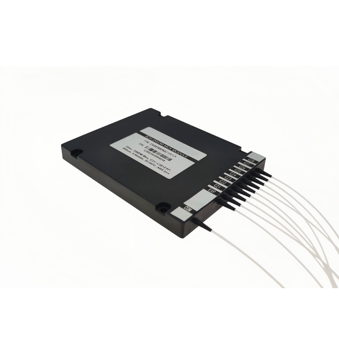
A 40 channel 100GHz athermal AWG manufacturer should be evaluated from the complete channel behavior, not from “40 channels” alone. Feiyi’s 40-CH 100G Athermal AWG is a C-band MUX/DEMUX product built for DWDM transmission, wavelength routing and optical add/drop applications. The product page lists 40 channels at 100 GHz spacing, a clear-channel passband of ±12.5 GHz, wavelength stability of ±0.005 nm, 1 dB bandwidth of 0.4 nm, 3 dB bandwidth of 0.24 nm, typical insertion loss of 4.5 dB and maximum insertion loss of 6 dB.
For a real network design, the buyer should first freeze the transceiver grid and passband requirement. Then check isolation, insertion-loss budget, profile shape, temperature range and package. The phrase “100 GHz AAWG” defines the channel spacing, but it does not tell an engineer whether the module has enough usable passband for the transmitter drift and filter cascade in the installed network.
A 40 channel 100GHz athermal AWG manufacturer should receive the full ITU channel plan
Feiyi identifies the operating region as C-band and the channel count as 40. A network engineer should provide the intended start and end channels rather than assume that every 40-channel system uses the same slice of the C-band. This becomes important when the AAWG must interoperate with existing muxes, transponders or OADM nodes.
The channel plan should also state whether the unit is used as a MUX, DEMUX or paired MUX/DEMUX. Feiyi’s ordering information includes those configuration choices, so the optical direction and port labeling should be agreed before rack integration.
Port labels should map to frequencies or wavelengths, not just Channel 1 through Channel 40
A numeric port label can become ambiguous when equipment from different vendors uses different starting-channel conventions. Put the actual ITU frequency or wavelength beside each used port in the handoff file. That prevents a physically correct patch from landing on the wrong DWDM carrier.
The ±12.5 GHz clear passband should be checked against transmitter drift and filter cascade
Feiyi lists a clear-channel passband of ±12.5 GHz. That number describes the usable central region around the channel, while the 100 GHz value describes center-to-center spacing. They solve different design questions. A buyer should compare the usable passband with the source spectrum, wavelength tolerance and any additional filters in the path.
External 100 GHz AAWG documentation also distinguishes Gaussian and flat-top profiles and treats passband as a core selection variable. Feiyi’s page describes this 40-channel specification as a Gaussian AAWG, so a project that specifically requires a flatter passband should compare it with Feiyi’s broader AWG family before freezing the module.
Gaussian profile is acceptable only when the system margin is built around its narrower useful center
A Gaussian filter can work well in a controlled DWDM link, but a network with larger wavelength drift or multiple cascaded filters may require more passband margin. The decision should come from the link budget and transmitter behavior, not from assuming one profile is universally better.
Insertion loss of 4.5 dB typical and 6 dB maximum belongs in the end-to-end optical budget
Feiyi’s table lists 4.5 dB typical insertion loss at the ITU grid and 6 dB maximum. A buyer should budget against the agreed worst-case value where service margin matters, then add connector, splice and other component losses separately. The AAWG cannot be approved from channel count if the remaining link power is already tight.
For a MUX/DEMUX pair, remember that the signal may pass through two AWG modules. Model the actual route rather than using one device loss for the whole span.
Adjacent and non-adjacent isolation should be evaluated from the neighboring traffic pattern
The Feiyi table lists adjacent-channel isolation of 25 dB, non-adjacent isolation of 29 dB and total channel isolation of 22 dB. These values describe different interference paths. A network with strong neighboring carriers may care most about adjacent isolation, while a dense multi-channel measurement may also watch total crosstalk across the module.
Do not convert the isolation table into one generic “high isolation” statement in the purchase file. Keep the values that matter to the actual channel loading and receiver sensitivity.
A partially populated 40-channel module should still preserve the full port map
A network may light only a subset of the forty channels at first. Keep the unused channel identities in the rack drawing so later expansion does not require reverse-engineering the original AWG port sequence.
Wavelength stability of ±0.005 nm should be read with the athermal operating concept
Feiyi lists wavelength stability of ±0.005 nm and an operating range from -5 to 65 °C, with storage from -40 to 85 °C. The athermal design is intended to maintain the wavelength grid without active temperature-control electronics. That makes the component useful in passive DWDM shelves where power and thermal-control complexity are undesirable.
External AAWG documentation similarly describes athermal AWGs as passive devices that do not require electrical temperature control. That is industry context, not a replacement for the Feiyi specification. The buyer should still qualify the Feiyi module across the environment required by the installed rack.
PDL and PMD should remain in the engineering handoff even when the network is not polarization maintaining
Feiyi lists polarization-dependent loss at 0.3 dB typical and 0.5 dB maximum and polarization-mode dispersion up to 0.5 ps in the displayed table. These parameters can affect high-performance optical links even when the transmission fiber itself is standard single-mode.
If the link budget or system test does not treat these values as limiting, keep them in the component record anyway. Removing them from the handoff makes future troubleshooting harder if the channel plan later carries a different transceiver generation.
Package and fiber routing should be decided before the 40-channel shelf is cabled
The Feiyi page lists a package around 120×70×10 mm and a screw-spacing dimension of 110×60 mm. Those values affect where the module can be mounted and how forty channel fibers leave the package. The rack layout should provide bend radius, labeling space and service access before the module arrives.
Feiyi’s ordering information includes fiber length and connector choices. A compact module can still create a difficult installation if channel fibers are too short to reach the panel or so long that they form unmanaged loops.
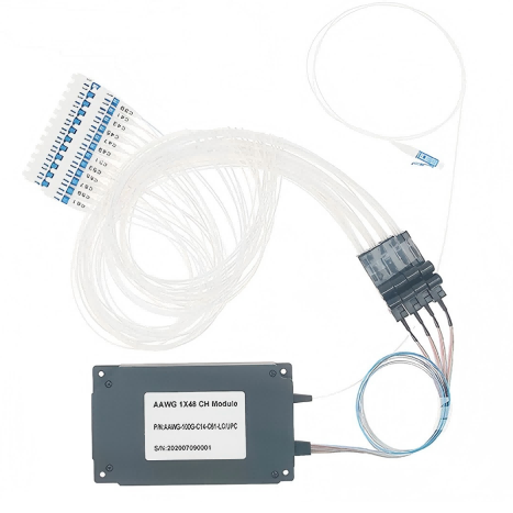
Connector choice should follow the shelf interface instead of being added after the optical design
Feiyi’s AWG ordering information includes FC/UPC, FC/APC, SC/UPC and SC/APC options, with other configurations available in the broader product family. The connector and polish should match the patch-panel or transceiver environment and should be captured in the channel map.
If the AWG is integrated inside a module rather than exposed at a rack panel, bare fiber or another pigtail arrangement may be more suitable. The buyer should choose the termination from the actual integration level.
The 1 dB and 3 dB bandwidth numbers should not be swapped in a design review
Feiyi lists a 1 dB channel bandwidth of 0.4 nm and a 3 dB bandwidth of 0.24 nm on the current page. Because the displayed relationship is unusual for conventional filter nomenclature, a buyer should confirm how these rows are defined before using them as acceptance limits. Do not silently “correct” the table from industry expectations; use the page as a prompt for supplier clarification.
The clear-channel passband of ±12.5 GHz is the safer directly stated parameter for initial system planning. If the network depends on the exact 1 dB or 3 dB width, ask for the current test definition or datasheet for the ordered profile.
Receiving inspection should verify channel identity before measuring one convenient port
For a forty-channel device, an optical test can pass on one port while the labeling or channel sequence is wrong elsewhere. Confirm the product identity, MUX/DEMUX configuration, start channel, channel spacing, connector type and port labels before sampling optical performance. If the customer requires every channel to be measured, define that in the order.
A useful first-article report can include insertion loss and wavelength alignment across the populated channels, with isolation checks on representative adjacent pairs. Repeat-production inspection can then follow the agreed sampling plan rather than inventing a new test method each lot.
A port-map error can create a network failure even when every individual filter meets loss
That is why the channel mapping belongs to quality inspection rather than only to installation documentation. The wrong wavelength on the right physical port is still a defective network interface.
A 40-channel 100GHz AAWG should be compared with 50GHz devices by capacity need, not by channel count alone
Feiyi also offers a 96-CH 50G Athermal AWG. The 50 GHz product doubles spectral density relative to 100 GHz spacing but brings a narrower channel environment and a different port-count and fiber-management problem. A network that only needs forty 100 GHz carriers may gain little from the extra density.
Conversely, a future network that needs more channels in the same optical band should evaluate the 50 GHz route at the system-design stage rather than waiting until the 40-channel shelf is full.
A repeat order should preserve the grid, passband interpretation and rack interface together
Once the first 40-channel module is approved, retain the 100 GHz spacing, channel plan, start/end channels, Gaussian profile, clear passband, agreed insertion-loss and isolation limits, MUX/DEMUX direction, temperature requirement, package, fiber lengths, connector polish and exact port labels. If Feiyi clarifies the 1 dB/3 dB bandwidth rows, attach that definition to the controlled item.
Feiyi’s existing AAWG passband article covers profile selection more broadly. This 40-channel article should remain the engineering handoff for a specific 100 GHz channel plan. A later buyer should be able to reconnect the same DWDM shelf without guessing how the forty ports were intended to map to the network.
Commissioning should prove the installed channel map rather than only the bare module
After the AAWG is mounted, verify the route through the actual patch panel and transceiver set. A module can arrive with correct optical specifications and still be integrated incorrectly if two patch leads are crossed or the rack labels use a different channel convention. Use a known source or wavelength meter to confirm several points across the grid, especially at the first, middle and last active channels.
For a phased deployment, document which ports are intentionally dark. That helps a later expansion team distinguish spare capacity from a failed or forgotten connection. The commissioning file should match the module port labels, rack labels and network planning sheet.
Service replacements should keep the same optical profile instead of matching only 40CH and 100GHz
A replacement module with forty 100 GHz channels can still behave differently if its profile, start channel, passband or connector plan changes. The maintenance BOM should therefore include the Gaussian profile and the approved channel range, not just the product family. If a flat-top replacement is proposed later, treat it as an engineering change and review cascade behavior before installation.
This protects the network from a common maintenance shortcut: choosing a device that fits the rack and grid spacing but changes the filter shape that the link budget was built around.
[executed on device: SK-20260121JOTG (a251fff9-956e-47b5-9307-14fb53329ed2)]